
Page 76 - Antennas for Base Stations in Wireless Communications
P. 76
Base Station Antennas for Mobile Radio Systems 49
2.3.1.2 General Aspects of Radiating Element Design The achievement
of a well-controlled elevation pattern, stable with frequency, depends
on the quality of the impedance match of individual radiating elements.
Individual tiers should have a VSWR less than about 1.2:1 across the
band of interest. This is a stringent requirement, but unless it is met,
errors in the nominal radiating currents in each tier, created by the effect
of mismatch at the power dividers in the feed network, will seriously
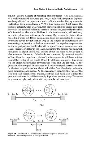
prejudice elevation pattern performance. The reason for this is illus-
trated in Figure 2.8. If two mismatched loads are connected to a simple
branched power divider, then so long as the lengths of transmission line
connecting the junction to the loads are equal, the impedances presented
at the output ports of the divider will be equal (though mismatched) and
equal currents will flow in the loads. Assuming the divider has been well
designed, its input VSWR will tend to about the same value as that of
the elements. However, if the loads are connected by unequal lengths
of line, then the impedance plots of the two elements will have rotated
round the center of the Smith Chart by different amounts, depending
on the electrical distances between the loads and the junction. At the
junction, the unequal impedances will cause unequal currents to flow
in the two output branches; these will differ from the design values in
both amplitude and phase. As the frequency changes, the ratio of the
complex load currents will change, so if the load mismatch is large the
power division ratio will be strongly dependent on frequency. The same
arguments apply to dividers with any number of branches.
z 2 z 1
z´ = z˝
z = z ≠ Z 0 z´ z˝ z = z ≠ Z 0
2
2
1
1
L 1 L 1
z´ z˝
Input
z 2 z 1
z´ ≠ z˝
z = z ≠ Z 0 z´ z˝ z = z ≠ Z 0
1
2
1
2
L 1 L > L 1
2
z´ z˝
Input
Figure 2.8 Illustration of the reason for the error in power division that
occurs if the load impedance is poorly matched