
Page 13 - Applied Process Design For Chemical And Petrochemical Plants Volume III
P. 13
66131_Ludwig_CH10A 5/30/2001 4:06 PM Page 3
Heat Transfer 3
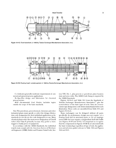
Figure 10-1C. Fixed tubesheet. (© 1988 by Tubular Exchanger Manufacturers Association, Inc.)
Figure 10-1D. Floating head—outside packed. (© 1988 by Tubular Exchanger Manufacturers Association, Inc.)
C—Indicates generally moderate requirements of com- tion VIII, Div. 1, plus process or petroleum plant location
mercial and general process applications. state and area codes. The ASME Code Stamp is required by
B—Specifies design and fabrication for chemical the TEMA Standards.
process service. Figures 10-1A—G and Table 10-1 from the Standards of
RGP—Recommended Good Practice, includes topics Tubular Exchanger Manufacturers Association 107 give the
outside the scope of the basic standards. nomenclature of the basic types of units. Note the nomen-
clature type designation code letters immediately below each
illustration. These codes are assembled from Table 10-1 and
Note: The petroleum, petrochemical, chemical, and other Figures 10-1A—G.
industrial plants must specify or select the design/fabrica- Many exchangers can be designed without all parts;
tion code designation for their individual application as the specifically the performance design may not require (a) a
standards do not dictate the code designation to use. Many floating head and its associated parts, or (b) an impinge-
chemical plants select the most severe designation of Class R ment baffle but may require a longitudinal shell side baffle
rather than Class B primarily because they prefer a more (see Figures 10-1F and 10-1G). It is important to recognize
rugged or husky piece of equipment. that the components in Figures 10-1B—K are associated with
In accordance with the TEMA Standards, the individual the basic terminology regardless of type of unit. An applica-
vessels must comply with the American Society of Mechani- tion and selection guide is shown in Table 10-2 and Figures
cal Engineers (ASME) Boiler and Pressure Vessel Code, Sec- 10-2 and 10-3.