
Page 191 - Applied Process Design For Chemical And Petrochemical Plants Volume III
P. 191
66131_Ludwig_CH10E 5/30/2001 4:33 PM Page 154
154 Applied Process Design for Chemical and Petrochemical Plants
q q
2
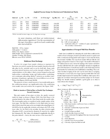
Interval t g (°F) t o (°F) 1/U t (1/U t) avg.* q (Btu/hr) A (ft ) t t avg. (°F) *
1U t2 avg. t avg.
135 to 135 100.0 0.0001359 . . . . . . . . . 41.4 . . . . . .
130 to 130 98.5 0.0001585 0.0001472 179,640 26.5 37.0 39.2 4,580
125 to 125 97.0 0.0001842 0.0001713 213,940 36.6 32.7 34.8 6,140
115 to 115 94.5 0.0002695 0.0002268 358,540 81.2 23.9 28.4 12,620
104 104 91.7 0.000518 0.0003937 314,730 123.6 14.0 18.9 16,650
________ _____ ______
1,066,850 267.9 39,990
*If the interval becomes large, use the log mean average.
(in some situations, and these are indeterminate where
without prior experience). For the uncertainties of D 1 O.D. of inner tube, ft
this type of problem, a preferred and considerably D 2 I.D. of outer pipe, ft
safer unit would be: r h hydraulic radius, ft (radius of a pipe equivalent to
the annulus cross-section)
Shell I.D. 25 in. (same)
Tube passes 4 (same) Approximation of Scraped Wall Heat Transfer
Tubes: 1-in. duplex (same)
Tube length: 32 ft (compared to assumed 24 ft) Little data is available for estimating the inside film coefficient for
Number of tubes: 109 (same) vessels or heat exchangers, heated externally by steam in a jacket and
2
2
Effective area: 870 ft (645 ft ) with a continuous moving inside wall scraper to clear away the heavy,
viscous inside wall film. The exact heat transfer will vary with the unit
Multizone Heat Exchange design and speed of rotation of the scraper. The studies of Ramdas et
95
al. indicate that to some extent the mixing of the warmer and lower
To select the proper heat transfer relations to represent the
viscosity wall fluid with the cooler and higher viscosity is a significant
functions, you need to analyze the heat transfer functions that will
part of the limitation of overall heat transfer to the fluid mass and that
take place in the unit-tube and/or on the shell side. Some units
may have several functions, such as the example in Rubin’s 179 rec- heat transfer by conduction in the bulk fluid is controlling. They con-
clude that slow scraping of the wall may be better than no scraping,
ommendations on this subject; that is, steam desuperheating and
but beyond a certain limit, the scraper speed provides little film heat
hydrocarbon condensing; steam and hydrocarbon condensing,
and condensate subcooling. Rubin 180 presents an excellent inter- transfer improvement. For laminar flow conditions, which quite often
apply, the correlation developed is somewhat unique for the Votator
pretation of multizone operation for several different sets of con-
design but should certainly establish a good guide as to what to
ditions. See Figures 10-91A and 10-91B.
expect from other designs.
The presence of even a small amount of noncondensable gas in
the condensing mixture can significantly reduce the condensing
0.059 0.113 0.063 0.018 (10-128)
heat transfer rates and needs to be recognized. See Figure 10-85. N u 57Re f Re f P r V isr
where (terms are all in consistent units)
Fluids in Annulus of Tube-in-Pipe or Double Pipe Exchanger,
Nu h s D r /k
Forced Convection
Re r ND t /
This unit consists of two pipes or tubes, the smaller centered Re f 4W/( ) (D t D s ) } dimensionless
P r C p /k
inside the larger as shown in Figure 10-92. One fluid flows in the groups
V isr / w
annulus between the tubes; the other flows inside the smaller tube.
0.0016 Re f 9.23
The heat transfer surface is considered as the outside surface of the
0.0164 Re r 68.65
inner pipe. The fluid film coefficient for the fluid inside the inner
h s film heat transfer coefficient from correlation
tube is determined the same as for any straight tube using Figures 10- D t tube diameter
46–10-52 or by the applicable relations correcting to the O.D. of the k thermal conductivity of process fluid
inner tube. For the fluid in the annulus, the same relations apply N shaft speed
(Equation 10-47), except that the diameter, D, must be the equiva- density of process fluid
lent diameter, D e . The value of h obtained is applicable directly to bulk viscosity of process fluid
the point desired — that is, the outer surface of the inner tube. 70 W mass continuous throughput flow rate of process fluid
3.1416
D s shaft diameter
2 2
D 2 D 1 41flow area2
D e 4r h (10-127) C p specific heat of process fluid
1wetted perimeter2
D 1 w viscosity of process fluid at wall