
Page 193 - Applied Process Design For Chemical And Petrochemical Plants Volume III
P. 193
66131_Ludwig_CH10F 5/30/2001 4:35 PM Page 156
156 Applied Process Design for Chemical and Petrochemical Plants
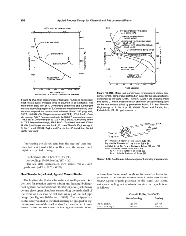
Figure 10-91B. Steam and condensate temperatures versus con-
denser length. Temperature distribution curve for the same multizone
condenser as in Figure 10-91A. Points A, E, and F are the same. Point
Figure 10-91A. High pressure boiler feedwater multizone condenser:
heat release curve. Pressure drop is assumed to be negligible. Hot B is above C, which locates the start of the wet desuperheating zone
fluid (steam side) inlet at A. Condensing completed and submerged on the tube surface. (Used by permission: Rubin, F. L. Heat Transfer
surface subcooling begins at E. Counter-current flow steam and con- Engineering, V. 3, No. 1, p. 49, ©1981. Taylor and Francis, Inc.,
densate temperatures versus heat released. Steam 350 psig inlet, Philadelphia, PA. All rights reserved.)
700°F, 1365.5 Btu/lb; 350 psia saturated 431.72°F, 1203.9 Btu/lb. Con-
densate out 340°F. Desuperheating in the 268.3°F temperature range,
161.6 Btu/lb. Condensing at 431.72°F, 794.2 Btu/lb. Subcooling in the
91.72°F temperature range, 986.0 Btu/lb. Total heat removed 1054.4
Btu/lb. (Used by permission: Rubin, F. L. Heat Transfer Engineering, V.
3, No. 1, p. 49, ©1981. Taylor and Francis, Inc., Philadelphia, PA. All
rights reserved.)
Interpreting the plotted data from the authors’ tests indi-
cates that heat transfer film coefficients at the scraped wall
might be expected to range:
2
For heating: 20—40 Btu/hr/(ft ) (°F)
2
For cooling: 10—30 Btu/hr/(ft ) (°F) Figure 10-92. Double-pipe tube arrangement showing annulus area.
The test data represented corn syrup, red oil, and
golden oil, (API 19.7 at 60°F)
Heat Transfer in Jacketed, Agitated Vessels/Kettles as is so often the required condition for some batch reaction
processes. Expected heat transfer overall coefficients for esti-
The heat transfer that is achieved in externally jacketed ket- mating typical organic processes in the vessel with steam,
tles used for reaction and/or mixing and heating/boiling/ water, or a cooling methanol-water mixture in the jackets are
cooling varies considerably with the style of jacket. Jackets may as follows:
be one piece open chambers surrounding the main shell of
the vessel, or they may be coil style, usually of the half-pipe Overall, U, Btu/hr(ft ) (°F)
2
design (see Figures 10-93A and 10-93B). The half-pipes are Steam heating Cooling
continuously welded to the shell and may be grouped in seg-
ments or sections of the shell to allow for the rather rapid con- Open jacket 25—55 25—40
version of a section from external heating to external cooling, Coils, half-pipe 25—80 30—55