
Page 198 - Applied Process Design For Chemical And Petrochemical Plants Volume III
P. 198
66131_Ludwig_CH10F 5/30/2001 4:35 PM Page 161
Heat Transfer 161
Table 10-24
Allowable Water Velocities in Tubes
Tube Minimum* Maximum Preferred
Fluid Material Velocity, ft/sec Velocity, ft/sec Velocity, ft/sec
Sea 70-3-Cupro- 2.5—3 12 6—8
water nickel;
0.5% Iron
Sea 90-10-Cupro- 2.5—3 10 6—8
water nickel;
1.25% Iron
Sea Aluminum 2.5—3 8 5—6
water brass
Brackish Steel 2.5 5 4
water
Treated well Steel 2.5 8—10 5—6
water Figure 10-95A. Heat flux for boiling water at 212°F. (Used by permis-
rd
Cooling Steel 2.5 8 6 sion: McAdams, W. H. Heat Transmission, 3 Ed., ©1954. McGraw-
tower Hill Book Co. All rights reserved.)
recirculated
water
*Do not design below these values.
The coefficient, h m , is to be used with the length mean t.
In streamline flow, 4 G / t 2,000:
5>3 1>3 1>9
h a c f 4G¿
0.67a b a b (10-137)
2>3 1>3
3 2 2 k a L g f
2k f g> f
where h a film
coefficient based on arithmetic mean t
Table 10-24 is an experience guide for reasonable service
using the types of water indicated inside tubes of the mater-
ial listed.
Sinek and Young 160 present a design procedure for pre-
dicting liquid-side falling film heat transfer coefficients
within 20% and overall coefficients within 10%.
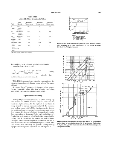
Vaporization and Boiling
Boiling of liquids occurs as nucleate or as film boiling. Fig-
ures 10-95A and 10-95B illustrate a typical flux curve for
water and hydrocarbons. In the region 1—2, the liquid is
being heated by natural convection; in 2—3 the nucleate
pool boiling occurs with bubbles forming at active sites on
the heat transfer surface, natural convection currents set up,
Q/A varies at t where n is 3—4, and the peak flux is at point
n
3 corresponding to the critical t for nucleate boiling; at 3
film boiling begins; and at 4—5—6 film boiling occurs. In film
boiling heat is transferred by conduction and radiation
through a film on the heating surface. Note that the rate of
Figure 10-95B. Heat transfer behavior of a mixture of hydrocarbon
effective heat transfer decreases beyond point 3, and it is for
fuels. (Used by permission: Jens, W. H. Mechanical Engineering,
this reason that essentially all process heating/boiling V. 76, Dec. 1954, p. 981. ©American Society of Mechanical Engineers.
equipment is designed to operate to the left of point 3. All rights reserved.)