
Page 200 - Applied Process Design For Chemical And Petrochemical Plants Volume III
P. 200
66131_Ludwig_CH10F 5/30/2001 4:35 PM Page 163
Heat Transfer 163
Figure 10-96A. Horizontal thermosiphon reboiler. a. Recirculating
feed system. b. Once-through feed system. Both are natural circula-
tion. (Used by permission: Yilmaz, S. B. Chemical Engineering
Progress, V. 83, No. 11, ©1987. American Institute of Chemical Engi-
neers. All rights reserved.)
Figure 10-96D. Vertical recirculation thermosiphon reboiler.
Figure 10-96B. Horizontal thermosiphon reboiler on distillation col-
umn: shell and tube design, not kettle. Boiling in shell.
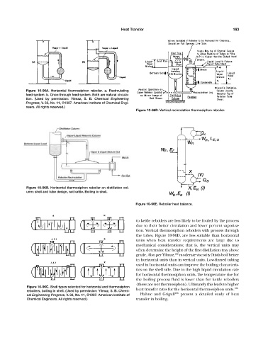
Figure 10-96E. Reboiler heat balance.
to kettle reboilers are less likely to be fouled by the process
due to their better circulation and lower percent vaporiza-
tion. Vertical thermosiphon reboilers with process through
the tubes, Figure 10-96D, are less suitable than horizontal
units when heat transfer requirements are large due to
mechanical considerations; that is, the vertical units may
often determine the height of the first distillation tray above
grade. Also per Yilmaz, 186 moderate viscosity fluids boil better
in horizontal units than in vertical units. Low-finned tubing
used in horizontal units can improve the boiling characteris-
tics on the shell side. Due to the high liquid circulation rate
for horizontal thermosiphon units, the temperature rise for
the boiling process fluid is lower than for kettle reboilers
(these are not thermosiphon). Ultimately this leads to higher
Figure 10-96C. Shell types selected for horizontal and thermosiphon 186
reboilers, boiling in shell. (Used by permission: Yilmaz, S. B. Chemi- heat transfer rates for the horizontal thermosiphon units.
186
cal Engineering Progress, V. 83, No. 11, ©1987. American Institute of Hahne and Grigull present a detailed study of heat
Chemical Engineers. All rights reserved.) transfer in boiling.