
Page 204 - Applied Process Design For Chemical And Petrochemical Plants Volume III
P. 204
66131_Ludwig_CH10F 5/30/2001 4:35 PM Page 167
Heat Transfer 167
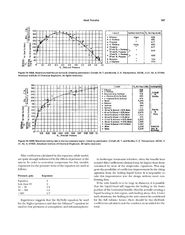
Figure 10-102A. Maximum heat flux (or burnout). (Used by permission: Cichelli, M. T. and Bonilla, C. E. Transactions. AIChE., V. 41, No. 6, ©1945.
American Institute of Chemical Engineers. All rights reserved.)
Figure 10-102B. Maximum boiling rate in the low pressure region. (Used by permission: Cichelli, M. T. and Bonilla, C. E. Transactions. AlChE, V.
41, No. 6, ©1945. American Institute of Chemical Engineers. All rights reserved.)
Film coefficients calculated by this equation, while useful,
are quite strongly influenced by the effects of pressure of the In kettle-type horizontal reboilers, often the bundle heat
system. In order to somewhat compensate for this, variable transfer film coefficients obtained may be higher than those
exponents for the pressure term of the equation are used as calculated by most of the single-tube equations. This sug-
follows: gests the possibility of coefficient improvement by the rising
agitation from the boiling liquid below. It is impossible to
Pressure, psia Exponent take this improvement into the design without more con-
firming data.
Equation 2
If the tube bundle is to be large in diameter, it is possible
Less than 10 2
10 30 1.9 that the liquid head will suppress the boiling in the lower
30 300 1.8 portion of the horizontal bundle; thereby actually creating a
300 1.7 liquid heating in this region, with boiling above this. Under
such situations, the boiling in the unit cannot be considered
Experience suggests that the McNelly equation be used for the full volume; hence, there should be two shell-side
53
for the higher pressures and that the Gilmour equation be coefficients calculated and the resultant areas added for the
used for low pressures of atmospheric and sub-atmospheric. total.