
Page 208 - Applied Process Design For Chemical And Petrochemical Plants Volume III
P. 208
66131_Ludwig_CH10F 5/30/2001 4:35 PM Page 171
Heat Transfer 171
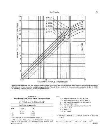
Figure 10-103A. Maximum heat flux: boiling outside horizontal tubes; kettle and internal reboilers. When using the estimate from this curve, a
safety factor of 0.7 also should be used. (Used by permission: Palen, J. W., and Small, W. M. Hydrocarbon Processing, V. 43, No. 11, ©1964.
Gulf Publishing Company, Houston, Texas. All rights reserved.)
Table 10-27 where
Tube Density Coefficient for 60° Triangular Pitch r w tube wall resistance, (hr)(ft)(°F)/Btu
a i tube inside heat transfer surface per ft, ft
[Tube Density Coefficient] [L/A] 0.5 a o tube outside heat transfer surface per ft, ft
T w tube wall thickness, ft
k wall thermal conductivity, Btu/(hr)(ft)(°F)
Coefficient for a given D o
p, in. 3 / 4 in. 1 in. D o tube O.D., ft
D i tube I.D., ft
1 0.196 — pi 3.1416
1.5 0.294 0.257
1.75 — 0.299 A. McNelly Equation, 90, 91, 189 overall deviation 50% and
L Bundle length, ft; bundle heat transfer surface, ft 2 40%:
Used by permission: Palen, J. W., and Small, W. M. Hydrocarbon Processing,
V. 43, No. 11, p. 199, ©1964. Gulf Publishing Company, Houston, Texas. h 1 0.225 C s 1g c l > 2 0.69 1144Pk 1 > 2 0.31 3 l > v 2 14 0.33
All rights reserved. (10-152)