
Page 202 - Applied Process Design For Chemical And Petrochemical Plants Volume III
P. 202
66131_Ludwig_CH10F 5/30/2001 4:35 PM Page 165
Heat Transfer 165
Vaporization in Horizontal Shell; Natural Circulation This is represented in Figures 10-98 and 10-99.
70
Kern deserves a lot of credit for developing design meth- where
ods for many heat transfer situations and in particular the k L thermal conductivity of saturated liquid,
natural circulation phenomena as used for thermosiphon Btu/hr (°F/ft)
reboilers and shown in part in Figures 10-96A—D. c L specific heat of liquid, Btu/lb (°F)
L liquid, lb/ft 3
The horizontal natural circulation systems do not use a ket-
v vapor, lb/ft 3
tle design exchanger, but rather a 1-2 (1 shell side, 2 tube-
2
surface tension of liquid, Btu/ft ;
side passes) unit, with the vaporized liquid plus liquid not 7 2
(dynes/cm) (0.88 10 ) Btu/ft
vaporized circulating back to a distillation column bottoms T temperature difference T w T s , °R
vapor space or, for example, to a separate drum where the
vapor separates and flows back to the process system and
where liquid recirculates back along with make-up “feed” to
the inlet of the horizontal shell and tube reboiler. See Fig-
ures 10-96A—C.
A large portion of vaporization operations in industry are
handled in the horizontal kettle unit. The kettle design is
used to allow good vapor disengaging space above the boil-
ing surface on the shell side and to keep tubesheet and head
end connections as small as possible. Services include vapor-
izing (reboiling) distillation column bottoms for reintro-
ducing the vapor below the first tray, vaporizing refrigerant
in a closed system (chilling or condensing on the process
steam side), and boiling a process stream at constant pres-
sure. The tube side may be cooling or heating a fluid or con-
densation of a vapor.
Physically the main shell diameter should be about 40%
greater than that required for the tube bundle only. This
allows the disengaging action.
The kettle unit used in the reboiling service usually has an
internal weir to maintain a fixed liquid level and tube cov-
erage. The bottoms draw-off is from the weir section. The
reboiling handled in horizontal thermosiphon units omits
the disengaging space because the liquid-vapor mixture Figure 10-98. Levy correlation for boiling heat transfer equation.
should enter the distillation tower where disengaging takes (Used by permission: Levy, S. ASME paper no. 58-HT-8, ©1958.
place. The chiller often keeps the kettle design but does not American Society of Mechanical Engineers. All rights reserved.)
use the weir because no liquid bottoms draw off when a
refrigerant is vaporized.
Pool and Nucleate Boiling—General Correlation for Heat
Flux and Critical Temperature Difference
77
Levy presented a correlation showing good agreement
for pool boiling and nucleate boiling heat transfer flux
(Q b /A) below the critical t for subcooled and vapor-
containing liquids. This covers the pressure range of sub- to
above-atmospheric and is obtained from data from the
inside and outside tube boiling.
3
2
Q b k L c L L 1 T2 31 x4
(10-139)
A ¿T s 1 L v 2B L
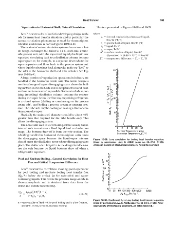
Figure 10-99. Coefficient B L in Levy boiling heat transfer equation.
x = vapor quality of fluid = 0 for pool boiling and is a low fraction, (Used by permission: Levy, S. ASME paper no. 58-HT-8, ©1958. Amer-
about 0.1 to 0.3, for most nucleate boiling ican Society of Mechanical Engineers. All rights reserved.)