
Page 20 - Applied Process Design For Chemical And Petrochemical Plants Volume III
P. 20
66131_Ludwig_CH10A 5/30/2001 4:06 PM Page 10
10 Applied Process Design for Chemical and Petrochemical Plants
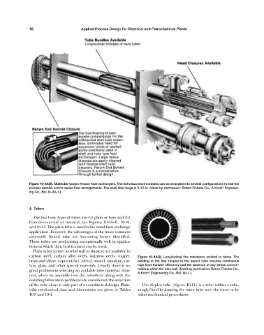
Figure 10-4A(2). Multitube hairpin fintube heat exchangers. The individual shell modules can be arranged into several configurations to suit the
®
process parallel and/or series flow arrangements. The shell size range is 3—16 in. (Used by permission: Brown Fintube Co., A Koch Engineer-
ing Co., Bul. B—30—1.)
4. Tubes
The two basic types of tubes are (a) plain or bare and (b)
finned—external or internal, see Figures 10-4A—E, 10-10,
and 10-11. The plain tube is used in the usual heat exchange
application. However, the advantages of the more common
externally finned tube are becoming better identified.
These tubes are performing exceptionally well in applica-
tions in which their best features can be used.
Plain tubes (either as solid wall or duplex) are available in
carbon steel, carbon alloy steels, stainless steels, copper, Figure 10-4A(3). Longitudinal fins resistance welded to tubes. The
brass and alloys, cupro-nickel, nickel, monel, tantalum, car- welding of the fins integral to the parent tube ensures continuous
bon, glass, and other special materials. Usually there is no high heat transfer efficiency and the absence of any stress concen-
great problem in selecting an available tube material. How- trations within the tube wall. (Used by permission: Brown Fintube Co.,
A Koch Engineering Co., Bul. 80—1.)
®
ever, when its assembly into the tubesheet along with the
resulting fabrication problems are considered, the selection
of the tube alone is only part of a coordinated design. Plain- The duplex tube (Figure 10-11) is a tube within a tube,
tube mechanical data and dimensions are given in Tables snugly fitted by drawing the outer tube onto the inner or by
10-3 and 10-4. other mechanical procedures.