
Page 232 - Applied Process Design For Chemical And Petrochemical Plants Volume III
P. 232
66131_Ludwig_CH10G 5/30/2001 4:37 PM Page 195
Heat Transfer 195
For the first trial, assume 39% vaporization per pass. From
Figures 10-114 and 10-116 and for 0.49,
x R L 2 tp
0.13 0.34 — 11.35 —
0.26 — 15 — —
0.39 0.19 25 8.28 2.02
The circulation rate is calculated as shown in Equation 10-
181:
W T = {49.5 (24.80 - 11.35)}/
2
0.00821149.42 0.012 10.55215.7921152
+ 0.008 (0.37)(19.31)(65) + 0.442 (2.02)} = 162 (10-181)
W T 12.7 lbs.>sec.
Now, (W T )(x E ) 12.7 (0.39) 4.95 lb/sec vaporized,
which is very close to the required vaporization rate of
17,600 lb/hr (4.89 lb/sec). No further adjustment is
required at this point.
Heat Transfer Rate—Stepwise Method
Based on the calculated circulation rate of 12.7 lb/sec,
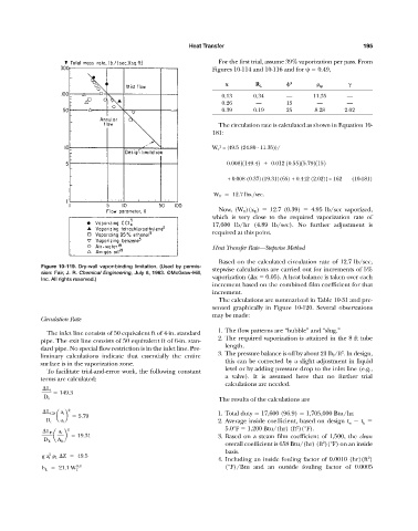
Figure 10-119. Dry-wall vapor-binding limitation. (Used by permis- stepwise calculations are carried out for increments of 5%
sion: Fair, J. R. Chemical Engineering, July 8, 1963. ©McGraw-Hill,
Inc. All rights reserved.) vaporization ( x 0.05). A heat balance is taken over each
increment based on the combined film coefficient for that
increment.
The calculations are summarized in Table 10-31 and pre-
sented graphically in Figure 10-120. Several observations
may be made:
Circulation Rate
1. The flow patterns are “bubble” and “slug.”
The inlet line consists of 50 equivalent ft of 4-in. standard
2. The required vaporization is attained in the 8 ft tube
pipe. The exit line consists of 50 equivalent ft of 6-in. stan-
length.
dard pipe. No special flow restriction is in the inlet line. Pre-
2
3. The pressure balance is off by about 21 lb f /ft . In design,
liminary calculations indicate that essentially the entire
this can be corrected by a slight adjustment in liquid
surface is in the vaporization zone.
level or by adding pressure drop to the inlet line (e.g.,
To facilitate trial-and-error work, the following constant
a valve). It is assumed here that no further trial
terms are calculated:
calculations are needed.
L i
149.3
The results of the calculations are
D i
2
L CD a i 1. Total duty 17,600 (96.9) 1,705,000 Btu/hr.
a b 5.79
2. Average inside coefficient, based on design t w t b
D t a t
2
5.0°F 1,200 Btu/(hr) (ft )(°F).
2
L E a i
a b 19.31 3. Based on a steam film coefficient of 1,500, the clean
D E A E 2
overall coefficient is 658 Btu/(hr) (ft )(°F) on an inside
basis.
2
g a i L Z 49.5 2
4. Including an inside fouling factor of 0.0010 (hr)(ft )
0.8 (°F)/Btu and an outside fouling factor of 0.0005
h L 21.1 W T