
Page 230 - Applied Process Design For Chemical And Petrochemical Plants Volume III
P. 230
66131_Ludwig_CH10F 5/30/2001 4:35 PM Page 193
Heat Transfer 193
parameter for two-phase physical properties, for use B. Heat Transfer: Simplified Method
with Figures 10-114, 10-115, 10-116, and 10-117. Fair recommends this method rather than his stepwise
Although is not constant, in general an average method given in the article, because it avoids increments of
constant value may be assumed. 45 calculations but is sufficiently reliable for most design cases.
10. Calculate the circulation rate, W T , by (see Table 10-29): This procedure is duplicated by permission. 45
See Table 10-29.
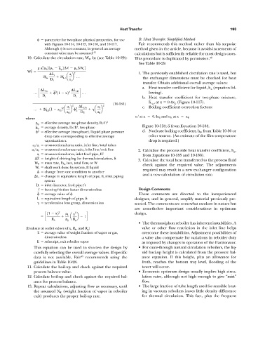
2
g a 1 L 31 L tp 2 Z L W s 4
W T
2
2 1. The previously established circulation rate is used, but
L i a i
2f Li 2f L t a b p the exchanger dimensions must be checked for heat
D i a t
transfer. Obtain additional overall average values:
a. Heat transfer coefficient for liquid, h L (equation fol-
L Bc 2 2 L cD
p c
11 x2 d p lowing).
D t D t
b. Heat transfer coefficient for two-phase mixture,
_
h tp , at x 0.4x E (Figure 10-117).
(10-181)
2 L DA a i 2 c. Boiling coefficient correction factors:
a i
2
2
p 2f LE 11 x E 2 a b
E a b
a E D E a E
where ' at x 0.4x E and E at x x E
tp effective average two-phase density, lb/ft 3 _
_
tp average density, lb/ft , two phase Figure 10-118; from Equation 10-184.
3
2
effective average (two-phase)/liquid phase pressure d. Nucleate boiling coefficient, h b , from Table 10-30 or
drop ratio corresponding to effective average other source. (An estimate of the film temperature
vaporization x drop is required.)
a i /a t cross-sectional area ratio, inlet line/total tubes
a i /a E cross-sectional areas ratio, inlet line/exit line 2. Calculate the process side heat transfer coefficient, h p ,
a i cross-sectional area, inlet feed pipe, ft 2 from Equations 10-185 and 10-186).
Z height of driving leg for thermal circulation, ft 3. Calculate the total heat transferred to the process fluid
W T mass rate, lb m /sec, total flow, or W check against the required value. The adjustments
W s shaft work done by system, ft liquid
change from one condition to another required may result in a new exchanger configuration
L i change in equivalent length of pipe, ft, inlet piping and a new calculation of circulation rate.
system
D i inlet diameter, feed pipe ft
_ f fanning friction factor dimensionless Design Comments
average value of
These comments are directed to the inexperienced
L equivalent length of pipe, ft designer, and in general, amplify material previously pre-
acceleration loss group, dimensionless sented. The comments are somewhat random in nature but
are nonetheless important considerations in optimum
11 x2 2 L x 2 design.
c a b 1d
R L g R g
• The thermosiphon reboiler has inherent instabilities. A
(Evaluate at outlet values of x, R L , and R g ) valve or other flow restriction in the inlet line helps
_
x average value of weight fraction of vapor or gas, overcome these instabilities. Adjustment possibilities of
dimensionless a valve also compensate for variations in reboiler duty
E subscript, exit reboiler vapor as imposed by changes in operation of the fractionator.
This equation can be used to shorten the design by • For once-through natural circulation reboilers, the liq-
carefully selecting the overall average values. If specific uid backup height is calculated from the pressure bal-
data is not available, Fair 45 recommends using the ance equation. If this height, plus an allowance for
guidelines in Table 10-28. froth, reaches the bottom tray level, flooding of the
11. Calculate the boil-up and check against the required tower will occur.
process balance value. • Economic optimum design usually implies high circu-
12. Calculate boil-up and check against the required bal- lation rates, although not high enough to give “mist”
ance for process balance. flow.
13. Repeat calculations, adjusting flow as necessary, until • The large fraction of tube length used for sensible heat-
the assumed X E (weight fraction of vapor in reboiler ing in vacuum reboilers leaves little density difference
exit) produces the proper boil-up rate. for thermal circulation. This fact, plus the frequent