
Page 225 - Applied Process Design For Chemical And Petrochemical Plants Volume III
P. 225
66131_Ludwig_CH10F 5/30/2001 4:35 PM Page 188
188 Applied Process Design for Chemical and Petrochemical Plants
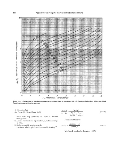
Figure 10-117. Design chart for two-phase heat transfer corrections. (Used by permission: Fair, J. R. Petroleum Refiner, Feb. 1960, p. 105. ©Gulf
Publishing Company. All rights reserved.)
A. Circulation Rate p B p 1 t> p2 s
See Figure 10-110 and Table 10-29. (10-170)
p B p A t> L t
a b
p> L p s
1. Select flow loop geometry, i.e., type of reboiler
arrangement.
From a heat balance:
2. Assume exit fractional vaporization, x E . Estimate range
15—40%.
D t N t h l 1t w t l 2
3. Evaluate sensible heating zone by T> L (10-171)
Fractional tube length devoted to sensible heating: 145 3,600W T c l
h l is from Dittus-Boelter Equation 10-175