
Page 224 - Applied Process Design For Chemical And Petrochemical Plants Volume III
P. 224
66131_Ludwig_CH10F 5/30/2001 4:35 PM Page 187
Heat Transfer 187
2
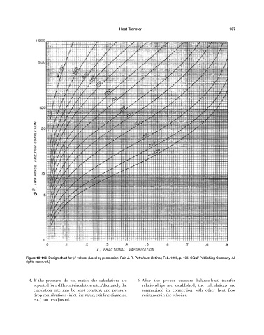
Figure 10-116. Design chart for
values. (Used by permission: Fair, J. R. Petroleum Refiner, Feb. 1960, p. 105. ©Gulf Publishing Company. All
rights reserved.)
4. If the pressures do not match, the calculations are 5. After the proper pressure balance-heat transfer
repeated for a different circulation rate. Alternately, the relationships are established, the calculations are
circulation rate may be kept constant, and pressure summarized in connection with other heat flow
drop contributions (inlet line value, exit line diameter, resistances in the reboiler.
etc.) can be adjusted.