
Page 220 - Applied Process Design For Chemical And Petrochemical Plants Volume III
P. 220
66131_Ludwig_CH10F 5/30/2001 4:35 PM Page 183
Heat Transfer 183
equations. These calculations are well suited to computer
application.
Select an increment of vaporization, beginning at the end
of the sensible heat zone. Use an average value of x for the
increment calculations. The circulation rate that must be
already developed on the basis of average conditions should
be used for the initial calculations.
45
Following Fair’s method outlined in the article, deter-
mine, select, or assume the following based on process
requirements (reproduced by permission of the author and
publisher, all rights reserved):
1. Boil-up rate.
2. Reboiler outlet temperature, pressure, and composi-
tion.
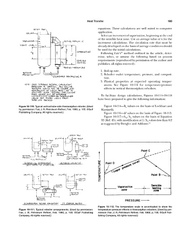
3. Physical properties at expected operating temper-
atures. See Figure 10-112 for temperature-pressure
effects in vertical thermosiphon reboilers.
To facilitate design calculations, Figures 10-114—10-118
have been prepared to give the following information:
Figure 10-110. Typical vertical tube-side thermosiphon reboiler. (Used Figure 10-114—R L values on the basis of Lockhart and
by permission: Fair, J. R. Petroleum Refiner, Feb. 1960, p. 105. ©Gulf Martinelli.
Publishing Company. All rights reserved.) Figure 10-116—
values on the basis of Figure 10-113.
2
Figure 10-117—h tp /h L values on the basis of Equation
32 (Ref. 45), with modification at 1/X tt values less than 0.2
as suggested by Dengler and Addoms. 12
Figure 10-112. The temperature scale is accentuated to show the
Figure 10-111. Typical reboiler arrangements. (Used by permission: temperature-pressure effects in themosiphon reboilers. (Used by per-
Fair, J. R. Petroleum Refiner, Feb. 1960, p. 105. ©Gulf Publishing mission: Fair, J. R. Petroleum Refiner, Feb. 1960, p. 105. ©Gulf Pub-
Company. All rights reserved.) lishing Company. All rights reserved.)