
Page 216 - Applied Process Design For Chemical And Petrochemical Plants Volume III
P. 216
66131_Ludwig_CH10F 5/30/2001 4:35 PM Page 179
Heat Transfer 179
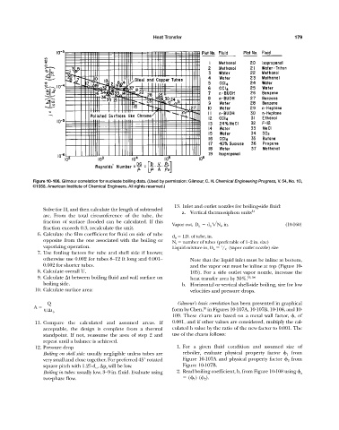
Figure 10-106. Gilmour correlation for nucleate boiling data. (Used by permission: Gilmour, C. H. Chemical Engineering Progress, V. 54, No. 10,
©1958. American Institute of Chemical Engineers. All rights reserved.)
13. Inlet and outlet nozzles for boiling-side fluid:
Solve for H c and then calculate the length of subtended 54
a. Vertical thermosiphon units
arc. From the total circumference of the tube, the
fraction of surface flooded can be calculated. If this
Vapor out, D n d it 2N t , in. (10-160)
fraction exceeds 0.3, recalculate the unit.
6. Calculate the film coefficient for fluid on side of tube
d it I.D. of tube, in.
opposite from the one associated with the boiling or N t number of tubes (preferable of 1—2 in. size)
vaporizing operation. Liquid mixture in, D n / 2 (vapor outlet nozzle) size
1
7. Use fouling factors for tube and shell side if known;
otherwise use 0.002 for tubes 8—12 ft long and 0.001— Note that the liquid inlet must be inline at bottom,
0.002 for shorter tubes. and the vapor out must be inline at top (Figure 10-
8. Calculate overall U. 105). For a side outlet vapor nozzle, increase the
9. Calculate t between boiling fluid and wall surface on heat transfer area by 30%. 53, 54
boiling side. b. Horizontal or vertical shell-side boiling, size for low
10. Calculate surface area: velocities and pressure drops.
Q Gilmour’s basic correlation has been presented in graphical
A 26
U t b form by Chen, in Figures 10-107A, 10-107B, 10-108, and 10-
109. These charts are based on a metal wall factor,
, of
11. Compare the calculated and assumed areas. If 0.001, and if other values are considered, multiply the cal-
acceptable, the design is complete from a thermal culated h value by the ratio of the new factor to 0.001. The
standpoint. If not, reassume the area of step 2 and use of the charts follows:
repeat until a balance is achieved.
12. Pressure drop 1. For a given fluid condition and assumed size of
Boiling on shell side: usually negligible unless tubes are reboiler, evaluate physical property factor
1 from
very small and close together. For preferred 45° rotated Figure 10-107A and physical property factor
2 from
square pitch with 1.25 d o , p s will be low. Figure 10-107B.
Boiling in tubes: usually low, 3—9 in. fluid. Evaluate using 2. Read boiling coefficient, h, from Figure 10-108 using
x
two-phase flow. (
1 ) (
2 ).