Page 221 - Applied Process Design For Chemical And Petrochemical Plants Volume III
P. 221

66131_Ludwig_CH10F  5/30/2001 4:35 PM  Page 184


                       184                       Applied Process Design for Chemical and Petrochemical Plants

                                                                             Process Requirements

                                                                               1. From fractionator calculations list
                                                                                 a. Boilup rate.
                                                                                 b. Reboiler outlet temperature, pressure, and compo-
                                                                                    sition.
                                                                               2. Obtain physical property data:
                                                                                 a. Liquid and gas (vapor) densities,   L and   g .
                                                                                 b. Liquid and gas (vapor) viscosities,   L and   g .
                                                                                 c. Liquid specific heat, c L .
                                                                                 d. Liquid thermal conductivity, k L .
                                                                                 e. Latent heat of vaporization,  .
                                                                                 f.  Surface tension,  .
                                                                                 g. Slope of vapor pressure curve, ( t/ p) s .
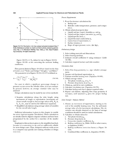
                       Figure 10-113. The factor 
 for two-phase turbulent-turbulent flow. 28
                       Note: Reference number on chart is in Fair’s article. (Used by permis-
                       sion: Fair, J. R. Petroleum Refiner, Feb. 1960, p. 105. ©Gulf Publish-  Preliminary Design
                       ing Company. All rights reserved.)
                                                                               1. Select tubing material and dimensions.
                                                                               2. Select heating medium.
                                                                               3. Estimate overall coefficient U using resistance (Table
                           Figure 10-115—1/X tt values for use in Figure 10-118.  10-13B).
                           Figure 10-118—  for correcting the nucleate boiling  4. Calculate required surface and tube number.
                         coefficient.
                                                                             Circulation Rate
                         Flow pattern limits in Figure 10-118 are based on the data
                                                             11
                                                    40
                                    15
                       of Govier et al., Yoder and Dodge, Dengler, and Baker. 3  1. Select flow loop geometry, i.e., type reboiler arrange-
                                                                                 ment.
                         The parameter   in Figures 10-114—10-117 is defined as
                                                                               2. Assume exit fractional vaporization, x E .
                               0.5    0.1                                      3. Evaluate sensible heating zone (Equation 10-169).
                               g    L        X tt
                          a   b  a   b                             (10-168)    4. Obtain average values:
                                          1W L >W g 2 0.9
                               L     g
                                                                                 a. Two-phase density,   tp , at x E /3.
                                                                                 b. Pressure drop factor, 
 ,  at 2 x E /3.
                         For cases in which a significant percentage change in
                                                                               5. Obtain   tp and 
 for exit conditions.
                       pressure occurs across the reboiler tubes,   is not constant.
                                                                               6. Calculate circulation rate (Equation 10-173).
                       In general, however, an average constant value may be
                                                                               7. Calculate boilup and check against required value.
                       assumed.
                                                                               8. Repeat calculations, adjusting flow loop geometry if
                         Design calculations may be made by one of two methods:
                                                                                 necessary, until assumed x E gives the proper boilup
                                                                                 rate.
                         • Stepwise calculations along the tube length, using
                           increments of length or vaporization. Increments are  Heat Transfer—Stepwise Method
                           chosen small enough so that average values of R L , R g , 
,
                           X tt , h t , etc., may be used in the difference equations.  1. Choose an increment of vaporization, starting at the
                         • Simplified calculations using average values of variables  end of the sensible heating zone. Use the arithmetic
                           for the overall tube length.                          average value of x for increment calculations. The cir-
                                                                                 culation rate already obtained on the basis of average
                         Sufficient information is given in this chapter to enable  conditions should be used for initial calculations.
                       the more rigorous stepwise calculations. These calculations  2. Calculate or obtain values for
                       are ideally suited to digital computer solution and have been  a. Two-phase density,   tp .
                       programmed by the author for a machine of the smaller     b. Pressure drop factor, 
.
                       type.                                                     c. Convective transfer coefficient, h tp .
                         Emphasis in this section is given to the simplified method,  d. Boiling coefficient, h b (Table 10-30 or other source,
                       because it is convenient to use and yet sufficiently reliable  or Equation 10-185).
                       for most design cases. Thus, designers without ready access  e. Boiling coefficient correction factor,   (Figure 10-
                       to a computer may quickly rate existing reboilers or design  118).
                       new ones.                                                 f.  Combined film coefficient, h v (Equation 10-186).
   216   217   218   219   220   221   222   223   224   225   226