
Page 361 - Applied Process Design For Chemical And Petrochemical Plants Volume III
P. 361
66131_Ludwig_CH11A 5/30/2001 4:49 PM Page 318
318 Applied Process Design for Chemical and Petrochemical Plants
Tables 11-9, 11-10, and 11-11 give useful comparative data
for most of the common refrigerants.
Pressure, temperature, and enthalpy or total heat values
may be obtained from tables or diagrams covering each par-
ticular refrigerant. Table 11-12 presents a few comparative
values of boiling points (evaporator temperature) and cor-
responding pressures as taken from such data.
System Performance Comparison
Table 11-13 is a study of the physical properties of several
refrigerants indicating a common level of temperature oper-
ation of 0°F evaporator operation and 110°F condensing
temperature on the high pressure side. The comparison
includes an approximate evaluation of the centrifugal and
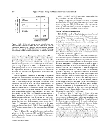
Figure 11-23. Refrigerant safety group classification, per reciprocating applications.
ANSI/ASHRAE Standard 34-1992, also see Table 11-3B. Used by Note that several CFC refrigerants are included, although
®
permission: ANSI/ASHRAE Standard 34-1992 including Addenda they are being phased-out and replaced by more environ-
®
34a–o and 34q–x, p. 5, ©1992, 1996. American Society of Heating, mentally safe refrigerants. These are left in the table at this
Refrigerating, and Air Conditioning Engineers, Inc. All rights reserved.
time because they have been such common/prominent
refrigerants in industrial applications.
important agreement. The agreement limited the 1988 pro- From Table 11-13, refrigerants no. 114, 11**, and 113 oper-
duction of certain CFCs and the levels of certain other halo- ate below atmospheric pressure in the evaporator and hence
12
genated compounds were “frozen” at 1986 levels. In 1994, at the suction side of the compressor. In general this is not a
the Copenhagen Amendment called for the production of good condition as it is likely to cause the in-leakage of air and
CFCs to stop by January 1, 1996, and the production of halo- moisture. Refrigerant 114 might be used in order to apply a
gens to stop by January 1, 1994. The hydrofluorocarbon centrifugal machine to a relatively low tonnage system, as
(HFC) refrigerants and their mixtures are not regulated by shown in column (H). Refrigerants 12 (soon to be phased-
the agreements. For other specific details not outlined in out, see Figure 11-24 [R-11]) and 114 have low condensing
this text, see Reference 20, Figure 11-24, and Tables 11-6, pressures, requiring less expensive condensers. In column
11-7, and 11-8. (B) the refrigerant may be selected based on boiling temper-
Table 11-4 presents tabulations of the safety of important ature at 14.7 psia. This indicates an operating pressure that
refrigerants, but this list does not include all available refriger- will prevent in-leakage of air. Actually, the suction pressure at
ants. Table 11-5 summarizes a limited list of comparative haz- the compressor flange will be below atmospheric pressure
ards to life of refrigerant gas and vapor. The current more unless proper allowances are made for the suction line pres-
applicable refrigerants from the major manufacturers of sure drop. This must be done if air in-leakage is to be avoided.
the CFC and HCFC refrigerants and their azeotropes/ Then the temperature at the evaporator will be increased by
blends/mixtures are included, but the list excludes the pure an amount corresponding to the temperature equivalent of
hydrocarbons such as propane, chlorinated hydrocarbons the pressure drop for the particular refrigerant. (Figure 11-25
such as methyl chloride and others, inorganics, ammonia, car- illustrates this point for R-12 refrigerant.)
bon dioxide, etc. See Table 11-6. The CFC compounds have a According to Table 11-7 and Figure 11-24, the refrigerant
longer and more serious ozone depletion potential than the R-11 was to have been phased-out by 1996. In principle the
HCFC compounds, because these decompose at a much lower same concept applies to other refrigerant applications as
atmospheric level and have relatively short atmospheric life- just described. Note that Figure 11-25 for Freon R-12 is used
times; therefore, they do less damage to the ozone layer. 28 for illustrative purposes, because R-12 was also to be phased-
Table 11-7 summarizes alternate refrigerants of the same out of availability in 1996 (production); however, similar
classes as discussed previously. Table 11-8 correlates DuPont’s useful charts can be constructed for other refrigerants.
®
SUVA refrigerant numbers to the corresponding ASHRAE Compression ratios of column (C) are considered as they
numbers. affect the limitations on the number of stages in a recipro-
Figure 11-24 provides a graphical representation of the cating machine or the number of wheels of a centrifugal
phase-out of the prominent CFC and HCFC refrigerants machine. The molecular weight is a rough guide as far as
and the timing for phasing in the availability of the respec- centrifugal compressor application is concerned, because
tive replacements. the higher molecular weight gases require fewer stages of
**Soon to be replaced by R-123.