
Page 123 -
P. 123
100 Part I Liquid Drilling Systems
liner to escape from the narrow drill pipe interior to the larger annulus
between the drill pipe and casing. Equipped with this tool, the system
now has two areas of fluid communication between the pipe interior and
the annulus: one at the bottom of the liner (autofill float equipment) and
one at the top of the liner (circulation sub). Displaced fluid seeks the
path of least resistance. This device helps to reduce the surge pressure
depending on the wellbore configurations and the location of the flow
diverter tool.
Numerical methods are used to obtain the correct flow split percen-
tage when communications exist between the pipe interior and the annu-
lus. The flow split is chosen such that the sum of hydrostatic and
frictional pressures in the pipe interior and through the bit (autofill float
equipment) will equal the sum of the hydrostatic and frictional pressures
in the annulus.
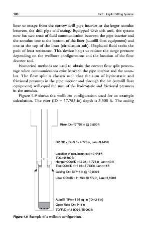
Figure 4.9 shows the wellbore configuration used for an example
calculation. The riser (ID = 17.755 in) depth is 3,500 ft. The casing
Riser ID = 17.755in @ 3,500ft
DP OD× ID= 5.5× 4.778 in, Len=9,445ft
Location of circulation sub = 9,445ft
TOL= 9,500 ft
Hanger OD× ID= 12.25 × 4.778in, Len=40ft
Tool OD× ID= 11.75× 4.778 in, Len=15ft
Casing ID = 12.715in @ 10,000ft
Liner OD × ID= 11.75× 10.772in, Len =5,500ft
Autofill, TFA= 4.91sq. in (ID= 2.5 in)
Open Hole ID= 14.5in
TD/TVD= 15,000ft /15,000ft
Figure 4.9 Example of a wellbore configuration.