
Page 127 -
P. 127
104 Part I Liquid Drilling Systems
0 50 100 150 200 250 300 350 400
0
2000
4000
String Depth (ft) 8000
6000
10000
Closed pipe
12000 TFA =0.1sq. in
TFA =0.3sq. in
14000 TFA =0.5sq. in
TFA =1.0sq. in
16000
Allowable Trip-In Speeds (ft/min)
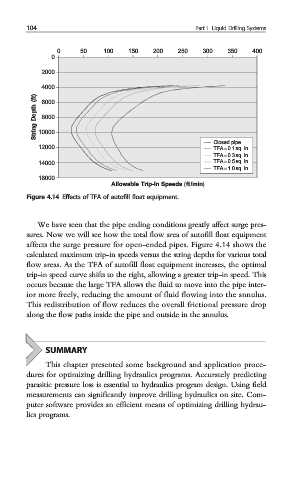
Figure 4.14 Effects of TFA of autofill float equipment.
We have seen that the pipe ending conditions greatly affect surge pres-
sures. Now we will see how the total flow area of autofill float equipment
affects the surge pressure for open-ended pipes. Figure 4.14 shows the
calculated maximum trip-in speeds versus the string depths for various total
flow areas. As the TFA of autofill float equipment increases, the optimal
trip-in speed curve shifts to the right, allowing a greater trip-in speed. This
occurs because the large TFA allows the fluid to move into the pipe inter-
ior more freely, reducing the amount of fluid flowing into the annulus.
This redistribution of flow reduces the overall frictional pressure drop
along the flow paths inside the pipe and outside in the annulus.
SUMMARY
This chapter presented some background and application proce-
dures for optimizing drilling hydraulics programs. Accurately predicting
parasitic pressure loss is essential to hydraulics program design. Using field
measurements can significantly improve drilling hydraulics on site. Com-
puter software provides an efficient means of optimizing drilling hydrau-
lics programs.