
Page 134 -
P. 134
112 Part II Gas Drilling Systems
Oxygen Out
Ambient Air In
Compressor(s) Water Filter
Oxygen
Hydrocarbon Filter Filter
Air Cooler Membrane
Particulate Filter
Membrane Skid
Booster(s)
Mist Pump
Nitrogen
into
Standpipe
Figure 5.4 A layout of the surface equipment in a nitrogen gas drilling system.
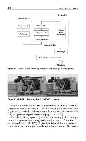
Figure 5.5 Air Drilling Specialties IR-XHP1170FSCAT compressor.
Figure 5.5 shows the Air Drilling Specialties IR-XHP1170FSCAT
compressor with an aftercooler. This compressor is a rotary screw type
3
(Lyons et al., 2001) that delivers air at a flow rate of 1,170 cfm (33 m /
min) in a pressure range of 150 to 375 psig (10 to 26 bar).
The blooey line (Figure 5.6) serves as a returning path for the gas
stream that contains rock cuttings and a small amount of fluids from the
formations (Hook et al., 1977). A pilot light is installed at the end of the
line to burn any natural gas from the returning gas stream. The blooey