
Page 159 - Applied Petroleum Geomechanics
P. 159
152 Applied Petroleum Geomechanics
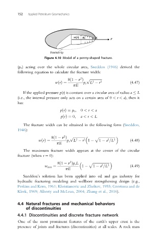
Figure 4.10 Model of a penny-shaped fracture.
(p 0 ) acting over the whole circular area, Sneddon (1946) derived the
following equation to calculate the fracture width:
2
8ð1 n Þ p ffiffiffiffiffiffiffiffiffiffiffiffiffiffi
2
wðrÞ¼ p o L r 2 (4.47)
pE
If the applied pressure p(r) is constant over a circular area of radius a L
(i.e., the internal pressure only acts on a certain area of 0 < r < a), then it
has:
pðrÞ¼ p 0 ; 0 < r < a
pðrÞ ¼ 0; a < r < L
The fracture width can be obtained in the following form (Sneddon,
1946):
2 p
8ð1 n Þ ffiffiffiffiffiffiffiffiffiffiffiffiffiffi p ffiffiffiffiffiffiffiffiffiffiffiffiffiffiffiffiffiffiffi
2
2
wðrÞ¼ p o L r 2 1 1 a =L 2 (4.48)
pE
The maximum fracture width appears at the center of the circular
fracture (when r ¼ 0):
8ð1 n Þp o L p ffiffiffiffiffiffiffiffiffiffiffiffiffiffiffiffiffiffiffi
2
2
w max ¼ 1 1 a =L 2 (4.49)
pE
Sneddon’s solution has been applied into oil and gas industry for
hydraulic fracturing modeling and wellbore strengthening design (e.g.,
Perkins and Kern, 1961; Khristianovic and Zheltov, 1955; Geertsma and de
Klerk, 1969; Alberty and McLean, 2004; Zhang et al., 2016).
4.4 Natural fractures and mechanical behaviors
of discontinuities
4.4.1 Discontinuities and discrete fracture network
One of the most prominent features of the earth’s upper crust is the
presence of joints and fractures (discontinuities) at all scales. A rock mass