
Page 164 - Applied Petroleum Geomechanics
P. 164
Basic rock fracture mechanics 157
(A) (B) τ
τ y Δv
k
1
τ
v
0
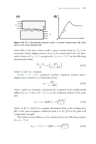
Figure 4.16 (A) A discontinuity sheared under a constant normal stress; (B) shear
stress versus shear displacement.
where DV j is the joint closure under a given normal stress s n ; V m is the
maximum closure (displacement); and s i is the initial stress level. An alter-
native version of Eq. (4.52) was given by Goodman (1976) in the following
dimensionless form:
t
s n s i DV j
¼ C (4.53)
s i V m DV j
where C and t are constants.
Bandis et al. (1983) proposed another empirical normal stresse
displacement model for an interlocked joint:
DV j
s n ¼ (4.54)
a bDV j
where a and b are constants; a represents the reciprocal of the initial normal
stiffness k ni (a ¼ 1/k ni ); a/b ¼ V m ; V m is the maximum closure of the joint
and
JCS
D
V m ¼ A þ BðJRCÞ þ C (4.55)
a j
where A, B, C, and D are constants determined from cyclic loading tests;
JRC is the joint roughness coefficient from 0 to 20; JCS is the joint wall
compression strength.
The initial normal stiffness can be obtained from the following relation
(Bandis, 1980):
JCS
k ni ¼ 7:15 þ 1:75JRC þ 0:02 (4.56)
a j