
Page 162 - Applied Petroleum Geomechanics
P. 162
Basic rock fracture mechanics 155
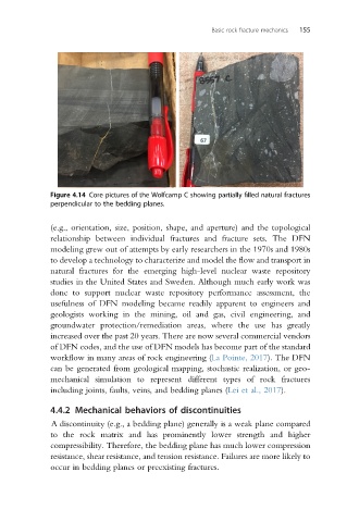
Figure 4.14 Core pictures of the Wolfcamp C showing partially filled natural fractures
perpendicular to the bedding planes.
(e.g., orientation, size, position, shape, and aperture) and the topological
relationship between individual fractures and fracture sets. The DFN
modeling grew out of attempts by early researchers in the 1970s and 1980s
to develop a technology to characterize and model the flow and transport in
natural fractures for the emerging high-level nuclear waste repository
studies in the United States and Sweden. Although much early work was
done to support nuclear waste repository performance assessment, the
usefulness of DFN modeling became readily apparent to engineers and
geologists working in the mining, oil and gas, civil engineering, and
groundwater protection/remediation areas, where the use has greatly
increased over the past 20 years. There are now several commercial vendors
of DFN codes, and the use of DFN models has become part of the standard
workflow in many areas of rock engineering (La Pointe, 2017). The DFN
can be generated from geological mapping, stochastic realization, or geo-
mechanical simulation to represent different types of rock fractures
including joints, faults, veins, and bedding planes (Lei et al., 2017).
4.4.2 Mechanical behaviors of discontinuities
A discontinuity (e.g., a bedding plane) generally is a weak plane compared
to the rock matrix and has prominently lower strength and higher
compressibility. Therefore, the bedding plane has much lower compression
resistance, shear resistance, and tension resistance. Failures are more likely to
occur in bedding planes or preexisting fractures.