
Page 122 - Applied Photovoltaics
P. 122
level LVD + LVDH is called the ‘low voltage reconnect’ (LVR) (Usher &
Ross, 1998).
Values for the setpoints depend on battery type, controller type and temperature. This
topic is treated in detail by Usher and Ross (1998).
There are two basic charging regulation methods to protect batteries against
overcharging, with many available variations (Usher & Ross, 1998).
Interrupting (on/off) regulation—the controller acts as a switch, allowing all
available PV current to the battery during charging. On reaching VR, the controller
switches off the charging current, by introducing either an open or short circuit. When
the voltage falls to VR – VRH, the current is reconnected. An alternative
reconnection strategy, aimed at avoiding rapid cycling, is to wait for a certain time
following disconnection. If the battery size is small compared to the PV array size,
on/off regulation can result in premature cessation of charge on sunny days. Then, the
high array current passing through the internal resistance of the battery produces a
high terminal voltage and VR can be reached before the battery is fully charged.
Constant voltage (constant potential) regulation. As for on/off regulation, the
available charging current is passed to the battery until VR is reached. Then however,
the charging current is tapered to ensure that the battery can store all the delivered
current. Some controllers modify the VR setpoint by sensing the battery condition or
using a low VR to avoid excessive gassing, coupled with provision for an occasional
gassing ‘equalisation’ charge. Several other variations are also used. Linear and pulse
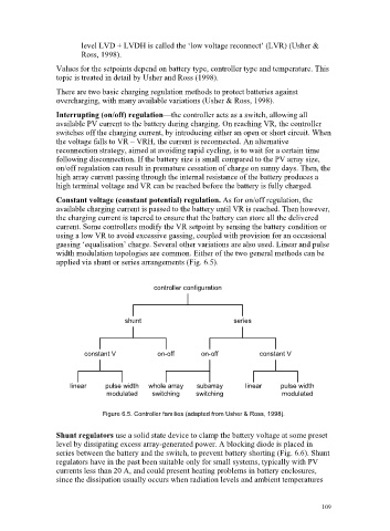
width modulation topologies are common. Either of the two general methods can be
applied via shunt or series arrangements (Fig. 6.5).
controller configuration
shunt series
constant V on-off on-off constant V
linear pulse width whole array subarray linear pulse width
modulated switching switching modulated
Figure 6.5. Controller families (adapted from Usher & Ross, 1998).
Shunt regulators use a solid state device to clamp the battery voltage at some preset
level by dissipating excess array-generated power. A blocking diode is placed in
series between the battery and the switch, to prevent battery shorting (Fig. 6.6). Shunt
regulators have in the past been suitable only for small systems, typically with PV
currents less than 20 A, and could present heating problems in battery enclosures,
since the dissipation usually occurs when radiation levels and ambient temperatures
109