Page 242 - Applied Photovoltaics
P. 242

drop in motor current accompanying a fall in light intensity on the solar
                                 panels affects both the field and armature windings. On the other hand, they
                                 tend to be able to pump more water than shunt DC motors on sunny days
                                 (Cultura, 2004).

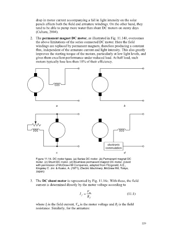
                              2. The permanent magnet DC motor, as illustrated in Fig. 11.14b, overcomes
                                 the above limitations of the series connected DC motor. Here the field
                                 windings are replaced by permanent magnets, therefore producing a constant
                                 flux, independent of the armature current and light intensity. This also greatly
                                 improves the starting torque of the motors, particularly at low light levels, and
                                 gives them excellent performance under reduced load. At half load, such
                                 motors typically lose less than 10% of their efficiency.


                                             a                                       b


                                                                           electronic
                                                                          commutation
                                             c                                       d

                                 Figure 11.14. DC motor types. (a) Series DC motor. (b) Permanent magnet DC
                                 motor. (c) Shunt DC motor. (d) Brushless permanent magnet DC motor. (Used
                                 with permission of McGraw-Hill Companies, adapted from Fitzgerald, A.E.,
                                 Kingsley C. Jnr. & Kusko, A. (1971), Electric Machinery, McGraw Hill, Tokyo,
                                 Japan)


                              3. The DC shunt motor is represented by Fig. 11.14c. With these, the field
                                 current is determined directly by the motor voltage according to

                                                               V
                                                           I    m                      (11.1)
                                                            f
                                                               R
                                                                 f
                                 where I f  is the field current, V m  is the motor voltage and R f  is the field
                                 resistance. Similarly, for the armature:


                                                                                                229
   237   238   239   240   241   242   243   244   245   246   247