
Page 247 - Applied Photovoltaics
P. 247
permanent magnet
PV panels DC voltage step-down DC motor as load
Q
L
R a
R S
C D
V L a
E
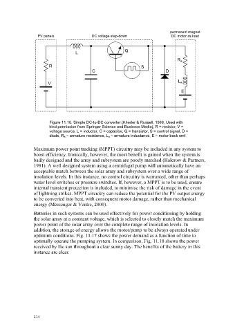
Figure 11.16. Simple DC-to-DC converter (Kheder & Russell, 1988, Used with
kind permission from Springer Science and Business Media), R = resistor, V =
voltage source, L = inductor, C = capacitor, Q = transistor, S = control signal, D =
diode, R a = armature resistance, L a = armature inductance, E = motor back emf.
Maximum power point tracking (MPPT) circuitry may be included in any system to
boost efficiency. Ironically, however, the most benefit is gained when the system is
badly designed and the array and subsystem are poorly matched (Halcrow & Partners,
1981). A well designed system using a centrifugal pump will automatically have an
acceptable match between the solar array and subsystem over a wide range of
insolation levels. In this instance, no control circuitry is warranted, other than perhaps
water level switches or pressure switches. If, however, a MPPT is to be used, ensure
internal transient protection is included, to minimise the risk of damage in the event
of lightning strikes. MPPT circuitry can reduce the potential for the PV output energy
to be converted into heat, with consequent motor damage, rather than mechanical
energy (Messenger & Ventre, 2000).
Batteries in such systems can be used effectively for power conditioning by holding
the solar array at a constant voltage, which is selected to closely match the maximum
power point of the solar array over the complete range of insolation levels. In
addition, the storage of energy allows the motor/pump to be always operated under
optimum conditions. Fig. 11.17 shows the power demand as a function of time to
optimally operate the pumping system. In comparison, Fig. 11.18 shows the power
received by the sun throughout a clear sunny day. The benefits of the battery in this
instance are clear.
234