
Page 318 - Applied Photovoltaics
P. 318
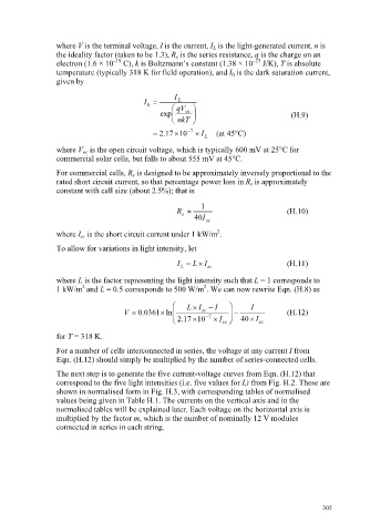
where V is the terminal voltage, I is the current, I L  is the light-generated current, n is
                          the ideality factor (taken to be 1.3), R s  is the series resistance, q is the charge on an
                                                                              –23
                                         –19
                          electron (1.6 × 10  C), k is Boltzmann’s constant (1.38 × 10  J/K), T is absolute
                          temperature (typically 318 K for field operation), and I 0  is the dark saturation current,
                          given by
                                                         I L
                                                 I
                                                  0     § qV  ·
                                                     exp¨   oc  ¸                       (H.9)
                                                        © nkT  ¹
                                                       . 2  17u 10   7  u I  (at  45q C)
                                                                 L
                          where V oc  is the open circuit voltage, which is typically 600 mV at 25°C for
                          commercial solar cells, but falls to about 555 mV at 45°C.

                          For commercial cells, R s is designed to be approximately inversely proportional to the
                          rated short circuit current, so that percentage power loss in R s is approximately
                          constant with cell size (about 2.5%); that is
                                                                1
                                                          R |                          (H.10)
                                                           s
                                                              40 I
                                                                 sc
                                                                    2
                          where I sc is the short circuit current under 1 kW/m .
                          To allow for variations in light intensity, let

                                                          I    L u  I                  (H.11)
                                                           L      sc
                          where L is the factor representing the light intensity such that L = 1 corresponds to
                                 2                               2
                          1 kW/m and L = 0.5 corresponds to 500 W/m . We can now rewrite Eqn. (H.8) as
                                                         §  L u  I    I  ·   I
                                                 .
                                            V   0361 u ln ¨     sc      ¸              (H.12)
                                                0
                                                         ¨        7     ¸    u
                                                         ©  . 2  17 u10  u  I sc ¹  40  I sc
                          for T = 318 K.
                          For a number of cells interconnected in series, the voltage at any current I from
                          Eqn. (H.12) should simply be multiplied by the number of series-connected cells.

                          The next step is to generate the five current-voltage curves from Eqn. (H.12) that
                          correspond to the five light intensities (i.e. five values for L) from Fig. H.2. These are
                          shown in normalised form in Fig. H.3, with corresponding tables of normalised
                          values being given in Table H.1. The currents on the vertical axis and in the
                          normalised tables will be explained later. Each voltage on the horizontal axis is
                          multiplied by the factor m, which is the number of nominally 12 V modules
                          connected in series in each string.


                                                                                                305