
Page 89 - Applied Photovoltaics
P. 89
ª § qV · º
I total MI L MI 0 « exp ¨ total ¸ 1 » (5.1)
¬ © nkTN ¹ ¼
+
PC
–
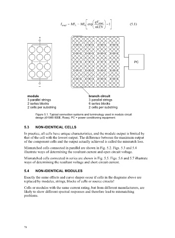
module branch circuit
3 parallel strings 3 parallel strings
2 series blocks 6 series blocks
2 cells per substring 2 cells per substring
Figure 5.1. Typical connection systems and terminology used in module circuit
design (©1980 IEEE, Ross). PC = power conditioning equipment.
5.3 NON-IDENTICAL CELLS
In practice, all cells have unique characteristics, and the module output is limited by
that of the cell with the lowest output. The difference between the maximum output
of the component cells and the output actually achieved is called the mismatch loss.
Mismatched cells connected in parallel are shown in Fig. 5.2. Figs. 5.3 and 5.4
illustrate ways of determining the resultant current and open circuit voltage.
Mismatched cells connected in series are shown in Fig. 5.5. Figs. 5.6 and 5.7 illustrate
ways of determining the resultant voltage and short circuit current.
5.4 NON-IDENTICAL MODULES
Exactly the same effects and curve shapes occur if cells in the diagrams above are
replaced by modules, strings, blocks of cells or source circuits!
Cells or modules with the same current rating, but from different manufacturers, are
likely to show different spectral responses and therefore lead to mismatching
problems.
76