
Page 108 - APPLIED PROCESS DESIGN FOR CHEMICAL AND PETROCHEMICAL PLANTS, Volume 1, 3rd Edition
P. 108
94 Applied Process Design for Chemical and Petrochemical Plants
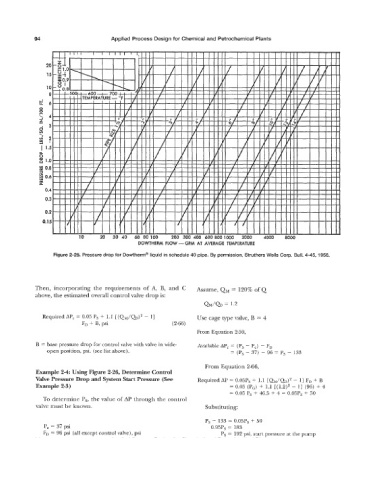
Figure 2-25. Pressure drop for Dowtherm@ liquid in schedule 40 pipe. By permission, Struthers Wells Gorp. Bull. 4-45, 1956.
Then, incorporating the requirements of A, B, and C Assume, QM = 120% of Q
above, the estimated overall control valve drop is:
Required APc = 0.05 Ps + 1.1 [(QI\.I/Q)~ 11 Use cage type valve, B = 4
-
F, + B, psi (2-66)
From Equation 2-59,
B = base pressure drop for control valve with valve in wide- Available APc = (Ps - P,) - F,
open position, psi. (see list above). = (Ps - 37) - 96 = Ps - 133
From Equation 2-66,
Example 24: Using Figure 2-26, Determine Control
Valve Pressure Drop and System Start Pressure (See Required AP = 0.05Ps + 1.1 [QM/QD)' - 11 FD + B
Example 2-3) = 0.05 (PG) + 1.1 [(1.2)' - 11 (96) + 4
= 0.05 Ps + 46.5 + 4 = 0.05Ps + 50
To determine P,, the value of AP through the control
valve must be known. Substituting:
Ps - 133 = 0.05Ps + 50
P, = 37 psi 0.95Ps = 183
FD = 96 psi (all except control valve), psi Ps = 192 psi, start pressure at the pump