
Page 109 - APPLIED PROCESS DESIGN FOR CHEMICAL AND PETROCHEMICAL PLANTS, Volume 1, 3rd Edition
P. 109
Fluid Flow 95
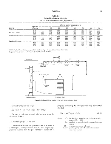
Table 2-9
Brine Pipe Friction Multiples
For Use With Water Friction Data, Figure 2-24
BRINE TEMPERATURE, “F
0 1 10 1 20 I 30 1
1 1.10 ... 1.23 1.20 1.18 1.16 1 1.22 I 1.21 j 1.12
BRINE Gravity 40 50 160-1
70
1.13
1.14
1.32 1
Sodium Chloride.. 1.15 1 i::; I 1.33 1.29 1.26 I 1.24 1.20
1.20 1.44 1.38 1.35 1.30 1.28 1.27
1.05 ... ... 1.15 1.12 1.10 1.08 1.07 1.06
I 1.10 ... 1.28 1.23 1.20 1.18 1.16 1.14 1.12
1.15 1.41 1.35 1.31 1.28 1.25 1.22 1.21 1.20
____ ____
Calcium Chloride. . . . . . . .
1.20 1.49 1.43 1.39 1.36 1.33 1.30 1.28 1.27
1.25 1.56 1.53 1.49 1.45 1.42 1.40 1.38 1.37
1.30 1.65 1.61 1.58 1.55 1.52 1.50 , 1.49 1.48
I I
NOTE: To find brine friction loss, multiply loss from Fig. 2-10 by multiplier from above Table.
By permission, Crocker, S., Piping Handbook, McGraw-Hill Book Go.
Charge liquid
r
22 psi
Trays this area
To vent control system
Separator
1 psi
Head = 15 psi (static)
Dlstillaticn column Fired heater 65 psi
Figure 2-26. Establishing control valve estimated pressure drop.
Control valve pressure drop: properly estimating the valve pressure drop. From Shin-
sky [101,
AP, = 0.05 Ps + 50 = 0.05 (192) -1 50 = 59.6 psi
-
GPM = a’(c%’ 4 (2 - 66)
Use this as estimated control valve pressure drop for )
the system design.
where a‘ = fractional opening of control valve, generally
assume 60% = 0.60
The Direct Oeszgn of a Control Valve C’, = standard valve coefficient from manufacturer’s
catalog
This does not require the system balance as outlined in APc = pressure drop across valve, psi
A through G above; however, without first preparing a SpGr = specific gravity of fluid, relative to water at
pressure balance, the designer cannot be confident of same temperature