
Page 112 - APPLIED PROCESS DESIGN FOR CHEMICAL AND PETROCHEMICAL PLANTS, Volume 1, 3rd Edition
P. 112
98 Applied Process Design for Chemical and Petrochemical Plants
The pressure that can develop from the shock wave can
be destructive to the containing system hardware, partic-
ularly in long pipe. Examples of conditions that can devel-
op water hammer are:
1. start, stop, or an abrupt change in a pump's speed
Straight pipe 90" Elbow 2. power failure
(Welding Type) 3. rapid closing of a valve (usually a control valve,
90" Elbow which can slam shut in one or two seconds)
Suction 3 [ 19, 201 :
J.
The magnitude of this shock wave can be expressed
-6'' Gate Valve
Full Open
Line
Centrifugal
(2-69)
Pump
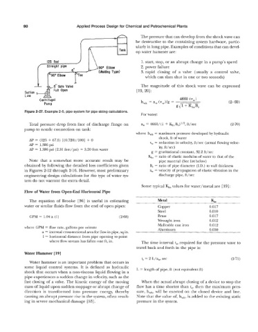
Figure 2-27. Example 2-5, pipe system for pipe sizing calculations.
For water:
Total pressure drop from face of discharge flange on a, 4660/ (1 + Qs B,)I/*, ft/sec (2-70)
pump to nozzle connection on tank:
where h,h = maximum pressure developed by hydraulic
shock, ft of water
AP = (125 + 67.5) [(0.720)/100] f 0
AP = 1.386 psi v, = reduction in velocity, ft/sec (actual flowing veloc-
ity, ft/sec)
AP = 1.386 psi (2.31 feet/psi) = 3.20 feet water
g = gravitational constant, 32.2 ft/sec
Q, = ratio of elastic modulus of water to that of the
Note that a somewhat more accurate result may be pipe material (See list below)
obtained by following the detailed loss coefficients given B, = ratio of pipe diameter (LD.) to wall thickness
in Figures 2-12 through 2-16. However, most preliminary a, = velocity of propagation of elastic vibration in the
engineering design calculations for this type of water sys- discharge pipe, ft/sec
tem do not warrant the extra detail.
Some typical &, values for water/metal are [ 191 :
Flow of Water from Open-End Horizontal Pipe
The equation of Brooke [36] is useful in estimating Metal Khs
water or similar fluids flow from the end of open pipes: Copper 0.017
Steel 0.010
GPM = 1.04 a (1) (2-68) Brass 0.017
Wrought iron 0.012
Malleable cast iron 0.012
where GPM = flow rate, gallons per minute
a = internal cross-sectional area for flow in pipe, sq in. Aluminum 0.030
1 = horizontal distance from pipe opening to point
where flow stream has fallen one ft, in. The time interval t,, required for the pressure wave to
travel back and forth in the pipe is:
Water Hammer [ 191
ts = 2 L/qv, sec (2-71)
Water hammer is an important problem that occurs in
some liquid control systems. It is defined as hydraulic L = length of pipe, ft (not equivalent ft)
shock that occurs when a non-viscous liquid flowing in a
pipe experiences a sudden change in velocity, such as the
fast closing of a valve. The kinetic energy of the moving When the actual abrupt closing of a device to stop the
mass of liquid upon sudden stoppage or abrupt change of flow has a time shorter than t,, then the maximum pres-
direction is transformed into pressure energy, thereby sure, hwh, will be exerted on the closed device and line.
causing an abrupt pressure rise in the system, often result- Note that the value of, hwh, is added to the existing static
ing in severe mechanical damage [53]. pressure in the system.