
Page 116 - APPLIED PROCESS DESIGN FOR CHEMICAL AND PETROCHEMICAL PLANTS, Volume 1, 3rd Edition
P. 116
102 Applied Process Design for Chemical and Petrochemical Plants
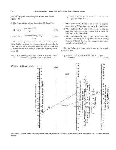
Friction Drop for Flow of Vapors, Gases, and Steam q'h = rate of flow, cu ft/hr at standard conditions (14.7
Figure 2-30 psia and 60"F), SCFH.
A. The Darcy rational relation for compressible $ow [3] is: 1. When calculated AP total < 10 percent inlet pres-
sure, use p orv based on inlet or outlet conditions.
0.000336 f W'V 2. When calculated AP total > 10 percent inlet pres-
AP / 100 ft = (2-77)
d5 sure, but < 40 percent, use average p orV based on
0.000001959f (q ) S ' inlet and outlet conditions.
or, AP / 100 ft = (2-78) 3. When calculated AP total, PI to P, is > 40% of inlet
d5p pressure, primarily for long lines, use the following
choices, or break the line into segments and calcu-
The general procedures outlined previously for han-
dling fluids involving the friction factor, f, and the k late AP for each as above.
chart are used with the above relations. This is applicable
to compressible flow systems under the following condi- Also use Babcock formula given in another paragraph
tions [3]. for steam flow.
where S, = specific gravity of gas relative to air = the ratio of q'h = 24,700 [Yd2/S,] (AP pl/K)'12, CFH @ 14.7 psia
molecular weight of the gas to that of air. and 60°F (2-79)
AP,, W
1600
APf100 ft. = 0.000 336 f Wz/dsp P V tl .4 i
loOa
.5
600
.6
40 I 8w
500
30 Inc 2 .7 100
.8
.04 .9 d 300
1.0
30 7 200
r 40
E50
Figure 2-30. Pressure drop in compressible flow lines. By permission, Crane Co., Technical Paper #474 Engineering Div. 1957. Also see 1976
edition.