
Page 114 - APPLIED PROCESS DESIGN FOR CHEMICAL AND PETROCHEMICAL PLANTS, Volume 1, 3rd Edition
P. 114
100 Applied Process Design for Chemical and Petrochemical Plants
SHEET NO.
LUDWIG CONSULTING ENGINEERS
BY ABC LINE SIZE SHEET Job No.
Date Charge No.
LP - 51
Line NO. Flow Sheet Drowipg No.
~
~
~i~~ ~ Reactor ~Discharge ~ i ~ ~ i ~ ~
Fluid in line Crude Product Temperature 280 OF
GPM (Calc.) 23.7 GPM (des.) 25 Pres sure 350 psig
CFM (Calc.) CFM (des.) Sp. Gr.O.93 -
L b s . /hr. (C a I c. ) L bs./hr.(des.) sp. VOl. cu.ft./lb.
S
Recommended Velocity 6.0 fP ___ Viscosity 0.91 CP
Straight pipe, fittings, valves Pressure. Drop
expansion, contraction, etc. Item in- pS I
Item No. Unit Eq. Ft. Total Eq. Ft. Pipe B Equivalent 5)
1
Pipe 254 4 254 L Ori fi ce 5 1 =10
s
Mator Valve (control 1 740
40
90OElbow
10
8
3
Tee
24
Mi scellaneaus
4
4
1
Gate Va.
Total i -
1
1
1
I
I
Total
f Rounded total to 75 feet !c Estimated line size erif ied)
By difference Actual Velocity 3.9 fp s
Inlet = 350 psig; Outlet = 0 psig Unit Lass per 100 ft. 1.52 Dsi (see below]
Friction Loss = 10 (includes orifice loss)
Balance for Valve = 340 psi Total head loss 869
in feet of liquid
Total pressure
drop in psi 350
Selected pipe sire 14" Material 8 Weight Schedule 40 steel
Calculations: Re = 50.6 QP/ dL= 50.6(25) (0.93 x 62.3)/(1.61) (0.91) = 50,025
b/d = 0.0012; f = :.02: (Figures 2-3 and 2-11)
AP/lOO' = 0,0216 f/3 Q2 / d5 = 0.0216(0.021) (62.3) (0.93) (25)*/(1.65)5
4
= 1.52 psi/lOO ft.
Total Pipe System Friction =((329)(1.52/100)) + 5" = 10 psi for friction; "Orifice
Total Loss, Feet Liquid = 350(2.3lft./psi)(l/0.93) = 869 feet of Liquid
Checked by: Dote:
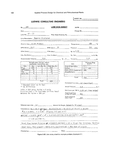
Figure 2-28. Line sizing sheet for example problem, Example 2-7.