
Page 139 - APPLIED PROCESS DESIGN FOR CHEMICAL AND PETROCHEMICAL PLANTS, Volume 1, 3rd Edition
P. 139
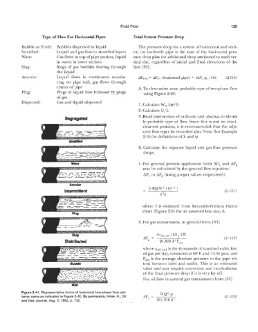
Fluid Flow                                           125

                                                                 Total System Pressure Drop


            Bubble OK Froth:  Bubbles dispersed in liquid           The pressure drop for a system of horizontal and verti-
            Stratified:     Liquid and gas flow in stratified layers   cal  (or inclined) pipe is the sum of the horizontal pres-
            Wave :          Gas flows in top of pipe section, liquid   sure drop plus the additional drop attributed to each ver-
                            in waves in lower section            tical rise, regardless of  initial and final elevations of  the
            Slug:           Slugs of gas bubbles flowing through   line 1331.
                             the liquid
            AnnUlar:        Liquid  flows  in  continuous  annular   APTP~ = APpT (horizontal pipe) + nhF,  pL/144   (2-110)
                            ring  on  pipe  wall,  gas flows through
                            clenter of pipe                         A. To determine most probable type of two-phase flow
            Plug:           Plugs of liquid flow followed by  plugs   using Figure 2-40.
                            of gas
            Dispersed:      Gas and liquid dispersed
                                                                    1. Calculate W,  hv/G
                                                                    2. Calculate G/h
                                                                    3. Read intersection of ordinate and abscissa to identi-
                                                                      + probable type of  flow. Since this is not an exact,
                                                                      clear-cut position, it is recommended  that the adja-
                                                                      cent flow types be recorded also. Note: See Example
                                                                      2-16 for definitions of h and ty.


                                                                    B. Calculate the separate liquid and gas flow pressure
                                                                      drops.

                                                                    1. For  general process application  both  APL and APg
                                                                      may be calculated by the general flow equation:
                                                                      APL or AP,  (using proper values respectively)


                                                                      - 3.36fLW2      )
                                                                      -                                      (2 - 111)
                                                                              d5p

                                                                      where  f  is  obtained  from  Reynolds-Friction Factor
                                                                      chart (Figure 2-3) for an assumed line size, d.

                                                                    2. For gas transmission, in general form [33]


                                                                                    Ls g TZf
                                                                             (9 d 14.65
                                                                      APp  =                                 (2 - 112)
                                                                              20,000 d5Pwg
                                                                      where qd 14.65 is the thousands of standard cubic feet
                                                                      of gas per day, measured at 60°F and 14.65 psia, and
                                                                      P,   is the average absolute pressure in the pipe sys-
                                                                      tem between inlet and outlet. This 6s  an estimated
                                                                      value and may require correction and recalculation
                                                                      of the final pressure drop if it is very far off.
                                                                      For oil flow in natural gas transmission lines [33]


              we 2-41. Represenlatiwe forms of  horizontal two-phase flow pat-   fLQ2 hp
           terns; same as indicated in Figure 2-40. By permission, Heim, H., Oil   APL. =                    (2-113)
           and Gas Journal, Aug. 2, 1982, Q. 132.                            181,916 d5