
Page 134 - APPLIED PROCESS DESIGN FOR CHEMICAL AND PETROCHEMICAL PLANTS, Volume 1, 3rd Edition
P. 134
120 Applied Process Design for Chemical and Petrochemical Plants
Pressure at end of line Table 2-15
= 0.01295 (379/18.02) (14.7) (1190/520) Dry-Gas Flow Transmission Factors
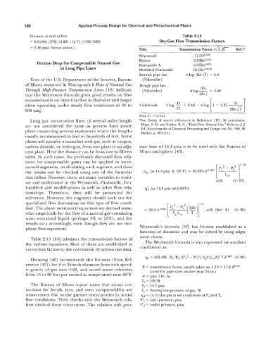
= 9.16 psia (below atmos.) Title Transmission Factor (fi/fr Ref.*
Weymouth 11.2~0~67
Friction Drop for Compressible Natural Gas Blasius 3.56Reo.lz5
Panhandle A
6.87Re0.075
in Long Pipe Lines Modified Panhandle 1 6.5Re0.OIg6
Smooth pipe law 4 log (Re fl) - 0.4
Tests of the U.S. Department of the Interior, Bureau (Nikuradse)
of Mines, reported in Monograph 6 Flow of Natural Gas Rough pipe law
Through High-pressure Transmission Lines [ 431 indicate (Nikuradse) 4 log- (D) + 3.48
that the Weymouth formula gives good results on flow (2E 1
measurements on lines 6 inches in diameter and larger r 1
D
when operating under steady flow conditions of 30 to Colebrook 4log - + 3.48 - 41og 1 + 9.35 ~
600 psig. 2E -
Note: D = inches
Long gas transmission lines of several miles length *See listing of source references in Reference [15]. By permission,
are not considered the same as process lines inside Hope, P. M. and Nelson, R. G., “Fluid Flow, Natural Gas,” McKetta, J. J.
plant connecting process equipment where the lengths Ed., Encyclopedia of Chemical Processing and Design, vol. 22, 1985, M.
Dekker, p. 304 [15].
usually are measured in feet or hundreds of feet. Some
plants will transfer a manufactured gas, such as oxygen,
carbon dioxide, or hydrogen, from one plant to an adja- sure base of 14.4 psia is to be used with the Bureau of
cent plant. Here the distance can be from one to fifteen Mines multipliers [43].
miles. In such cases, the previously discussed flow rela-
tions for compressible gases can be applied in incre-
mental segments, recalculating each segment, and then 2 - p,2 lli2
the results can be checked using one of the formulas qh (at 14.4 psia & 60°F) = 36.926 d2.667 p1
that follow. However, there are many variables to evalu- 1 Lm 1
ate and understand in the Weymouth, Panhandle, Pan- scfh (2-97)
handle-A and modifications as well as other flow rela- q’h (at 14.4 psia and 60°F)
tionships. Therefore, they will be presented for
reference. However, the engineer should seek out the
specialized flow discussions on this type of flow condi- 1 p,2 - ’,‘
tion. The above mentioned equations are derived some- = 28.0 d2.667 scfh (Ref. 8) (2-98)
what empirically for the flow of a natural gas containing s, Lm
some entrained liquid (perhaps 5% to 12%), and the
results vary accordingly, even though they are not two-
phase flow equations. Weymouth’s formula [57] has friction established as a
function of diameter and may be solved by using align-
ment charts.
Table 2-15 [ 151 tabulates the transmission factors of
the various equations. Most of these are established as The Weymouth formula is also expressed (at standard
correction factors to the correlation of various test data. conditions) as:
Dunning [40] recommends this formula (from Ref- qd 433.49E (T,/P,) [P’,’ - P’2‘]/SgTIL,Z] 1’2d2.667 (2- 99)
erence [43]) for 4 to 24-inch diameter lines with specif- E = transmission factor, usually taken as: 1.10 X 11.2
ic gravity of gas near 0.60, and actual mean velocities (omit for pipe sizes smaller than 24 in.)
from 15 to 30 feet per second at temperature near 60°F. d = pipe I.D., in.
T, = 520”R
The Bureau of Mines report states that minor cor- P, = 14.7 psia
rections for bends, tees, and even compressibility are T1 = flowing temperature of gas, “R
unnecessary due to the greater uncertainties in actual qd = cu ft/day gas at std conditions of P, and T,
line conditions. Their checks with the Weymouth rela- p’ - ’
1 - inlet pressure, psia
tion omitted these corrections. The relation with pres- P’z = outlet pressure, psia