
Page 129 - APPLIED PROCESS DESIGN FOR CHEMICAL AND PETROCHEMICAL PLANTS, Volume 1, 3rd Edition
P. 129
Fluid Flow 115
Table 2-14 For flow of gases and vapors through nozzles and orifices:
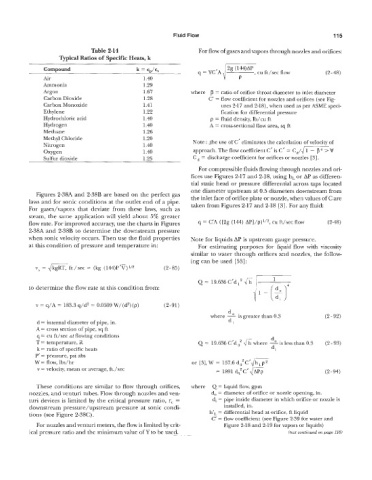
Typical Ratios of Specific Heats, k
Compound k = qc, q = YC’A , cu ft/sec flow (2-48)
Air 1.40
Ammonia 1.29
Argon 1.67 where p = ratio of orifice throat diameter to inlet diameter
Carbon Dioxide 1.28 C‘ = flow coefficient for nozzles and orifices (see Fig-
Carbon Monoxide 1.41 ures 2-17 and 2-18), when used as per MME speci-
Ethylene 1.22 fication for differential pressure
Hydrochloric acid 1.40 p = fluid density, lb/cu ft
Hydrogen I .40 A = cross-sectional flow area, sq ft
Methane 1.26
Methyl Chloride 1.20
Nitrogen 1.40 Note : fhe use of C’ eliminates the calculation of velocity of
Oxygen 1.40 approach. The flow coefficient C’ is C’ = C,/dmV
Sulfur dioxide 1.25 C = discharge coefficient for orifices or nozzles [ 31.
For compressible fluids flowing through nozzles and ori-
fices use Figures 2-17 and 2-18, using ht or AP as differen-
tial static head or pressure differential across taps located
one diameter upstream at 0.5 diameters downstream from
Figures 2-38A and 2-38B are based on the perfect gas
laws and for sonic conditions at the outlet end of a pipe. the inlet face of orifice plate or nozzle, when values of C are
taken from Figures 2-17 and 2-18 [3]. For any fluid:
For gases/vapors that deviate from these laws, such as
steam, the same application will yj,eld about 5% greater
flow rate. For improved accuracy, use the charts in Figures q = C’A ([2g (144) AP]/P)~’~, cu ft/sec flow (2-48)
2-38A and 2-38B to determine the downstream pressure
when sonic velocity occurs. Then use the fluid properties Note for liquids AP is upstream gauge pressure.
at this condition of pressure and temperature in: For estimating purposes for liquid flow with viscosity
similar to water through orifices and nozzles, the follow-
ing can be used [53]:
Q = 19.636C’dI2 &
to determine the flow rate at this condition from: y’ - (21
v = q/A = 183.3 q/‘d2 = 0.0509 W/‘(dz) (P) (2-91)
d
is
where 2 greater than 0.3 (2- 92)
d = internal diameter of pipe, in. di
A= cross section of pipe, sq ft
q = cu ft/sec at flowing conditions
do .
T = temperature, R Q = 19.636 C’d 02 fi where -is less than 0.3 (2-93)
k = ratio of specific heats di
P’ = pressure, psi ah
W = flow, Ibs/hr or [3], W = 157.6 dO2C’llh,p2
v = velocity, mean or average, ft./sec = 1891 dO2C’& (2-94)
These conditions are similar to flow through orifices, where Q = liquid flow, gpm
nozzles, and venturi tubes. Flow through nozzles and ven- do = diameter of orifice or nozzle opening, in.
turi devices is limited by the critical pressure ratio, r, = di = pipe inside diameter in which orifice or nozzle is
downstream pressure/upstream piressure at sonic condi- installed, in.
tions (see Figure 2-3SC) ~ hlL = differential head at orifice, ft liquid
C’ = flow coefficient (see Figure 2-39 for water and
For nozzles and venturi meters, the flow is limited by crit- Figure 2-18 and 2-19 for vapors or liquids)
ical pressure ratio and the minimum value of Y to be used. (text continued on page 118)