
Page 127 - APPLIED PROCESS DESIGN FOR CHEMICAL AND PETROCHEMICAL PLANTS, Volume 1, 3rd Edition
P. 127
Fluid Flow 113
I
d
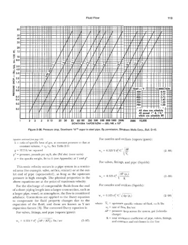
DOWTHERM VAPOR FLOW - LB$./HR. x 10’
we 2-36. pressure drop, C)owtherm “A”@ vapor in steel pipe. By permission, Struthers wells ~orp.,
(equatzon conlznuedfrom page 110) For nozzles and orifices (vapors/gases) :
k = ratio of specific heat of gas, at constant pressure to that at
constant volume, = cp/q,. See Table 2-14
g = 32.2 ft/sec squared W, = 0.525 Y d: 6’ AP (2-88)
p” = pressure, pounds per sq ft, abs (Psf abs) (note units)
p = the specific weight, lb/cu ft (see Appendix) at T and p”
For valves, fittings, and pipe (liquids)
This sonic velocity occurs in a pipe system in a restrict-
ed area (for example, valve, orifice, venturi) or at the out-
let end of pipe (open-ended), as long as the upstream
pressure is high enough. The physical properties in the (2-89)
above equations are at the point of maximum velocity.
For the discharge of compressible fluids from the end For nozzles and orifices (liquids) :
ofa short piping length into a larger cross section, such as
a larger pipe, vessel, or atmosphere, the flow is considered
adiabatic. Corrections are applied to the Darcy equation w, = 0.525 df C’dAp (pl) (2-90)
to compensate for fluid property changes due to the
expansion of the fluid, and these are known as U net where = upstream specific volume of fluid, cu ft/lbs
expansion factors [3]. The corrected Darcy equation is: ws = rate of flow, lbs/sec
AP = pressure drop across the system, psi (inlet-dis-
For valves, fittings, and pipe (vapors/gases) :
charge)
w, = 0.525Ydf fiP/( (2-87) K = total resistance coefficient of pipe, valves, fittings,
and entrance and exit losses in the line