
Page 122 - APPLIED PROCESS DESIGN FOR CHEMICAL AND PETROCHEMICAL PLANTS, Volume 1, 3rd Edition
P. 122
108 Applied Process Design for Chemical and Petrochemical Plants
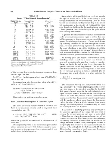
Table 2-13 Sonic velocity will be established at a restricted point in
Factor “F” For Babcock Steam Formula“ the pipe, or at the outlet, if the pressure drop is great
Nominal Pipe Size *Standard Weight #Extra Strong enough to establish the required velocity. Once the sonic
Inches Pipe Pipe velocity has been reached, the pressure drop in the system
% 955.1 x 2.051 x will not increase, as the velocity will remain at this value
% 184.7 x 340.8 x 10-3
1 45.7 x 10⁻³ 77.71 x 10⁻³ even though the fluid may be discharging into a vessel at
1% 9.432 x 10⁻³ 14.67 x 10⁻³ a lower pressure than that existing at the point where
1% 3.914 x 10⁻³ 5.865 x sonic velocity is established.
2 951.9 x 10⁻⁶ 1.365 x
2% 351.0 x 10⁻⁶ 493.8 x 10⁻⁶ In general, the sonic or critical velocity is attained for an
3 104.7 x 10⁻⁶ 143.2 x outlet or downstream pressure equal to or less than one
3% 46.94 x 10⁻⁶ 62.95 x
half the upstream or inlet absolute pressure condition of a
4 23.46 x 10⁻⁶ 31.01 x system. The discharge through an orifice or nozzle is usu-
5 6.854 x 10⁻⁶ 8.866 x
6 2.544 x 10⁻⁶ 3.354 x 10⁻⁶ ally a limiting condition for the flow through the end of a
8 587.1 10-9 748.2 x lO--9 pipe. The usual pressure drop equations do not hold at
10 176.3 x 10⁻⁹ 225.3 x the sonic velocity, as in an orifice. Conditions or systems
12 70.32 x 10⁻⁹ 90.52 x 10⁻⁹
exhausting to atmosphere (or vacuum) from medium to
14 O.D. 42.84 x 10⁻⁹ 55.29 x 10⁻⁹ high pressures should be examined for critical flow, other-
16 O.D. 21.39 x 10⁻⁹ 27.28 x 10⁻⁹
18 O.D. 11.61 x 10⁻⁹ 14.69 x 10⁻⁹ wise the calculated pressure drop may be in error.
20 O.D. 6.621 x 8.469 x 10-9 All flowing gases and vapors (compressible fluids)
24 O.D. 2.561 x 10⁻⁹ 3.278 10-9
including steam (which is a vapor) are limited or
*Factors are based upon I.D. listed as Schedule 40. approach a maximum in mass flow velocity or rate, Le.,
#Factors are based upon I.D. listed as Schedule 80. lbs/sec or lbs/hr through a pipe depending upon the
?By permission The Walworth Co. specific upstream or starting pressure. This maximum
rate of flow cannot be exceeded regardless of how much
the downstream pressure is further reduced [3]. To
of 8 inches, and then vertically down to the pressure drop determine the actual velocity in a pipe, calculate by
loss of 3.5 psi/IOO feet.
For 138 feet (no fittings or valves), total AP is 138 (3.5/ 3.06 W 7
100) = 4.82 psi. V= d2 or use Figure 2-34.
For comparison, solve by equation, using value of F =
587.1 X from Table 2-13. This maximum velocity of a compressible fluid in a
pipe is limited by the velocity of propagation of a pressure
AP/lOO ft = (1432)* (587.1 X 10-9)/0.364 wave that travels at the speed of sound in the fluid [3].
= 3.32 psi/lOO ft This speed of sound is specific for each individual gas or
AP total = (3.32/100) (138) = 4.75 psi vapor or liquid and is a function of the ratio of specific
heats of the fluid. The pressure reduces and the velocity
These values are within graphical accuracy. increases as the fluid flows downstream through the pipe,
with the maximum velocity occurring at the downstream
Sonic Conditions Limiting Flow of Gases and Vapors end of the pipe. When, or if, the pressure drop is great
enough, the discharge or exit or outlet velocity will reach
The sonic or critical velocity (speed of sound in the the velocity of sound for that fluid.
fluid) is the maximum velocity which a compressible fluid
can attain in a pipe [3]. If the outlet or discharge pressure is lowered further,
the pressure upstream at the origin will not detect it
v, = [(cp/cv) (32.2) (1544/MW) (460 + t)]l/z (2-84) because the pressure wave can only travel at sonic veloci-
= 68.1 [(cp/c,) P’/P]~/~, ft/sec ty. Therefore, the change in pressure downstream will not
be detected upstream. The excess pressure drop obtained
where the properties are evaluated at the condition of by lowering the outlet pressure after the maximum dis-
sonic flow. charge has been reached takes place beyond the end of
This applies regardless of the downstream pressure for the pipe [3]. This pressure is lost in shock waves and tur-
a fixed upstream pressure. This limitation must be evalu- bulence of the jetting fluid. See References 12,13,24, and
ated separately from pressure drop relations, as it is not 15 for further expansion of shock waves and detonation
included as a built in limitation. waves through compressible fluids.