
Page 126 - APPLIED PROCESS DESIGN FOR CHEMICAL AND PETROCHEMICAL PLANTS, Volume 1, 3rd Edition
P. 126
112 Applied Process Design for Chemical and Petrochemical Plants
snEEr NO.
LUDWIG CONSULTING ENGINEERS
BY LINE SIZE SHEET Job 210.
Date Charge No.
Line No. Lp - 61 Flow Sheet Drowi>ng No.
Vent through Exchanger for Tower T - 3
LineDescription
Np + Hydrocarbon
Fluid in line Temperature 140 OF
prig
GPM (Calc.) 2060 GPM (des.) 2270 Pressure 11.3 5.3 cu.ft./lb.
Sp. Gr. O.975
*
CFM (des.)
CFM (COIC.)
10,841
12,000
sp. Val.
Lbs./hr.(Colc.)
Lbs./hr.(des.)
Viscosity 0.019
Recommended Velocity
CP
fP ~
Total Eq. Ft.
No.
Unit Eq. Ft.
Item
5
St. 1 ine
I
I
1.56
Total
Total
Estimated line size Iott (existing)
Cross-sect. area, 10" pipe=O.547 sq.ft. Actual Velocity 41 r;n fp
Velocity = 2270/0.547 = 4150 Feet/Min. Unit ~ors per 100 ft. 0.0857 psi
Total head loss
in feet of liquid
Total pressure
drop in psi 1.56
Selected pipe size lo" Material L Weight Schedule 40, Steel
6.31 w = (6.31)(12,OOO) = 3.98 x 10⁵
Colculatians:& $
=
1
f = 0.0158 e= 1/0 CL
(0.000336) (fJ (WJ' - - UUUjjb, (U.m [ IZ,000JL. .
.AP/IOO feet = (10.02)5 (1/11.3)
-
= 0.0857 Psi/lOO equivalent feet of pipe(as pipe,fittings,valves, etc)
,AP Total (friction) = (0.0857/100)(72) = 0.0617 Psi
~
Checked by: Date:
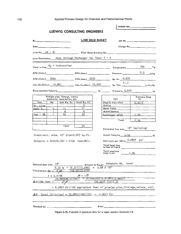
Figure 2-35. Example of pressure drop for a vapor system, Example 2-8.