
Page 128 - APPLIED PROCESS DESIGN FOR CHEMICAL AND PETROCHEMICAL PLANTS, Volume 1, 3rd Edition
P. 128
114 Applied Process Design for Chemical and Petrochemical Plants
Fluid Flow
0.1025 LV
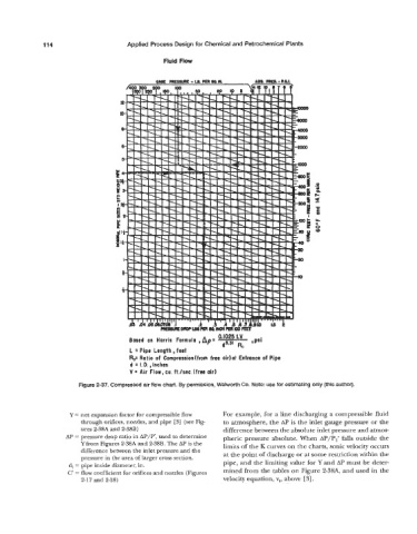
Based on Harris Formula ,Ap= d5.3, *Psi
RC
L = Pipe Length, feet
Rc= Ratio of Compression(from free airlat Entrance of Pipe
d = 1. D. , Inches
V = Air Flow, cu. ft./sec. (free air)
Figure 2-37. Compressed air flow chart. By permission, Walworth Co. Note: use for estimating only (this author).
Y = net expansion factor for compressible flow For example, for a line discharging a compressible fluid
through orifices, nozzles, and pipe PI (see Fig- to atmosphere, the AP is the inlet gauge pressure or the
ures 2-38A and 2-38B) difference between the absolute inlet pressure and atmos-
Ap pressure drop ratio in used to determine pheric pressure absolute. When AP/P,’ falls outside the
2-38A and 2-38B’ The is the limits of the K curves on the charts, sonic velocity occurs
difference between the inlet pressure and the at the point of discharge or at some restriction within the
pressure in the area of larger cross section.
di = pipe inside diameter, in. pipe, and the limiting value for Y and AP must be deter-
~
~
~
~
~
i
c’ = flow coefficient for and nozzles ( ~ mined from the tables on Figure 2-38A, and used in the
2-17 and 2-18) velocity equation, v,, above [ 31.