
Page 159 - APPLIED PROCESS DESIGN FOR CHEMICAL AND PETROCHEMICAL PLANTS, Volume 1, 3rd Edition
P. 159
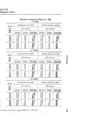
'Fable 2-22


 Friction losses in pipes carrying water
 Among  the many empirical formulae for friction  losses that have
 been  proposed  that  of  Williams and  IIaaen  has  been  most  widely
 used.  In a convenient  form it reads:
 in which
 f =  friction  head  tn  ft  of  liquid  per
 d4~5'365   100 ft of  pipe  (if  desired in  lb per
 sq in. multiply f X  .433 X  sp  gr)
 d-  inside dia of  pipe in  inches    Head loss 1  Velocity 1  Velocity  1  Headloas
 q=  flow in gal per min               ft per 100 ft  ft per sec   head ft   ft per 100 ft
 C = constant  accounting  for  surface                              I-
 roughness
 This  formula  gives  accurate  values  only  when  the  kinematic
 viscosity  of  the  liquid  is about  1.1 centistokes or 31.6 SSU, which
 is the case with water at about GOF. But the viscosity of  water varies
 with  the temperature from 1.8 at 32F to 29 centistokes at 212F.
 The tables are therefore  subject  to this  error  which  may  increase
 the friction  loss as much as 20% at 32F and decrease it as much as
 20%  at  212F.  Note  that  the  tables  may  be used  for  any liquid
 having  a  viscosity of  the same order as indicated above.   % Inch
 Values  of  C  for  various  types of  pipe  are given  below  together
 with  the corresponding multiplier  which  should apply to the tabu.   FLOW  I   STANDARD WT STEEL   EXTRA STRONG STEEL
 lated values of  the head loss, f.  as given on pages 29 to 48.
            us                                             .302" inside dia           L!
            gal    _______-__                                               -
            per
 I   VALUESOFC   mm   ft per scc   Velocity   ft per 100 ft  ft per scc.   Velocity   ft per 100 ft
                                                   Velocity
                                                                      Head loss
                    Velocity
                                       Head loss
                                                             head ft
                              head ft
 Range   Averag  3ommonly   0.4   1.23   .02   5.22   1.79     .05       13.0
 -
 used
                                .05
 High=   value   value for   0-6   1.85   .09   11.1   2.69    . 11      27-4
 for
                                                               .20
                                                                         46.1
             0-8
                      2.47
                                          18.8
                                                     3.59
 TYPE OF PIPE   best,   good,   design   1.0   3.08   .15   28.5   4.48   .31   70.6
 smooth,   clean,   purposes   1.2   3.71   .21   39.9   5.38   .45      98.9
 well laid   new
 -
 LOW=   pipe          4.33      .29       53.0       6.27
                                                     7.17
                                          67.9
                                .38
                      4.94
 poor or              5.55                           8.07
                                                     8.96
 Cement-Asbestos.  ........................................   160-140   -   140   6.17   11.2
                      7.71
 150
 150   140
 148   140                              3A  Inch
 150
 __   140
 -
 140
 Iooa-stave .................................................   -   130   STANDARD WT STEEL   GXTRA STRONG STEE4
 110
 120
 -.
 Welded and seamless steel.. ................................   150-80-   140   100
 Continuous-interior  riveted  steel  (no  projecting rivets  or)   .493" inside dia   .423" inside dia
 joints ..................................................   __   100
 bl  lrought-iron.. .............................................  I  150-80   100
 cast-iron.. .................................................   !P!--sO   100   ft per sec   head ft   It Per 100 ft  ft per sec   head ft   ft per 100 ft
                                                   Velocity  I  Velocity  I Head loss
                    Velocity  I  Velocity  1  Head loss
 Rdi-riveted steel (Droiectina rivets in girth and horizontal I=-  145-XU   -   100   0.8   1.31   .03   4.30   i.83   .05   13-7
 Tar-coated cast-iron. .......................................
 100
 Girth-riveted steel (projecting rivets in girth seams only).. .
 130
                                                                          9.107
 Concrete ...................................................
 100
 120
 152-85
                                                               .os
                                           6.50
             t -0
                                                     2.28
                      1.68
                                .04
 ..
 .................................................
 I
 seams)
                                                     4.67
 Vitrified.. ..................................................   115   100   1.6   3.43
 110
 100
 Spirakiveted steel (flow with lap).. ........................   110   100   2.6   36.4   5.71
 Spiral-riveted steel (flow against lap). ......................   90   1.0   5.05   ~  40   49.6   6.85   .73   106
 Corrugated steel.. ..........................................   60   11.4 9.14  1  sif  I  @
                                                     8.00
 Valueof C.. ....................   ..I  150 I 140 I la0  I  120  I 110  I 100  I  90  I  8   70   60   6.0   8.41   1.10   134
 ___-___-____---
 Multiplier to correct tables. %.  , . . , . lkd .54 1  .62 I  .?1 I .84 I  1.0 I  1.22 1  1.58 I  1.93 I 2.57   1.58   179   13.7   377
                                                                                      d
 *By perniission 6. V. Shaw and A. W. Loomis Cameron HydraulicData, 11th Edition, Ingersoll-Rand  Go., 1942 [531.   G