
Page 155 - APPLIED PROCESS DESIGN FOR CHEMICAL AND PETROCHEMICAL PLANTS, Volume 1, 3rd Edition
P. 155
Fluid Flow I41
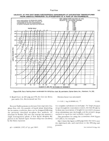
XIT WHEN DISCHARGING CONDENSATE AT SATURATION TEMPCRAT
'VARIOUS PRESSURES TO ATMOSPHERE AT A RATE OF 100 POUNDSiHR.
FOR LARGER PIPES MULTIPLY 3' PIPE
WHEN DISCHARGING TO PRESSURES HIGHER VELOCITY BY FOLLOWING FACTORS:
THAN ATMOSPHERIC, MULTIPLY VELOCITY TO PIPE FACTOR
ATMOSPHFRF BY FACTOR CORRESPONDING 4" 0.58
TO GPLY PRESSURE AND RECEIVER PRESSURE 5" 0.37
6" 0.25
Pa.
ure 2-54. Sarco flashing steam condensate line sizing flow chart. By permission, Spirax-Sarco, Inc., Ai~e~~~~n~
[59].
9. Read Chart: At 450 pig and 576, the line size shows Friction factor was calculated:
just under 2-in. Recommend use 2-in.
f = 0.25 [-log (0.000486/d)]-'~o (2-1 35)
Because flashing steam-condensate lines represent two- for complete turbulence in steel pipe. For large pressure
phase flow, with the quantity of liquid phase depending drops through the transmission system, the line should be
on the system conditions, these can be designed following broken into increments of length for successive pressure
the previously described two-phase flow methods. An drop calculations over the length, and the pressure drops
skin [28] uses the concept but assumes a summed to equal the total available/required.
single hornogeaeou,s phase of fine liquid droplets dis- The procedure for using the convenient chart Figure
persed in the flashed vapor. Pressure drop was calculated 2-55 [28] is, for example:
Step 1: Enter the figure at 600 psig below the insert near
the right-hand side, and read do~n to the 200-psig end-
pressure.
AP = 0.000336 (fme)/d5 (p), psi/lOO ft (2-55A) (text continued on page 153)