
Page 151 - APPLIED PROCESS DESIGN FOR CHEMICAL AND PETROCHEMICAL PLANTS, Volume 1, 3rd Edition
P. 151
Fluid Flow 137
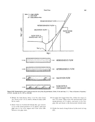
Note: V = mean velocity
L = pipe length
AP = total pressure drop
HOMOGENEOUS FLOW
HETEROGENEOUS FLOW
SALTATION FLOW
FLOW WITH A
STATIONARY BE
---* HOMOGENEOUS F
e. .... ...... ... ......_...
_3 : :....:, .:.....: : : ..,.. - HETEROGENEOUS F
4 - SALTATION FLOW
+ FLOW WITH A
STATIONARY BE
Figure 2-50. Representative plot of pressure drop for slurry flow. By permission, Turian, R. M. and Yuan, T. F., “Flow of Slurries in Pipelines,”
A.1.Ch.E. Journal, VQI. 23, 1 977, p. 232-24.3.
8. Divide the load factor (step 1) by the value from 10. For pipe sizes larger than 3h., follow the steps (1)
the “factor sca.le” of (7) above, obtain ft/min/ (100 thru (8) above. Then enter the vertical scale at the
Ib/hr load). steam pressure of (1) above, and more to the 3-in.
pipe size and down to the horizontal velocity scale.
9. Enter chart 011 horizontal velocity line, go vertical-
ly up to the steam pressure of (1) above, and read
pipe size to the next largest size if the value falls 11. Divide the result of step 8 above by the result of step
between two pipe sizes. (10).