
Page 147 - APPLIED PROCESS DESIGN FOR CHEMICAL AND PETROCHEMICAL PLANTS, Volume 1, 3rd Edition
P. 147
Fluid Flow 133
Table 2-21 The suction pressure required at the uacuurn pump (in
Criteria for Sizing Gomeeking Lines in Vacuum Service absolute pressure) is the actual process equipment operat-
ing pressure minus the pressure loss between the process
vacum primp Assumed flow velocity, ft/s
~____~.~_ equipment and the source of the vacuum. Note that absolute
Steam jet: pressures must be used for these determinations and not
System pressure, tori- gauge pressures. Also keep in mind that the absolute pres-
0.5-5 300 sure at the vacuum pump must always be a Bower absolute
5-25 250 pressure than the absolute pressure at the process.
25-150 200
150-760 150
Liquid ring pump: Pipe Sizing for Non-Newtonian
Single-stage" 100
Two-stage 150 Non-Newtonian fluids vary significantly in their prop-
Rotary piston: erties that control flow and pressure loss during flow from
Single-stage 50 the properties of Newtonian fluids. The key factors influ-
Two-stage 25 encing non-Newtonian fluids are their shear thinning or
Rotary vane:? thickening characteristics and time dependency of viscos-
Single-stage 200 ity on the stress in the fluid.
Two-stage 400 Most conventional chemical and petrochemical plants
Rotary blowers: do not process many, if any, non-Newtonian fluids. How-
Atmospheric discharge 50 ever, polymers, grease, heavy oils, cellulose compounds,
Discharging to backing pump 100
paints, fine chalk suspensions in water, some asphalts, and
"Assumes the pump features dual inlet connections and that an inlet other materials do exhibit one type QP another of the
manifoolcl will be used. characteristics of non-Newtonians, ciassified as:
+Based on rough vacuum process pumps. Use 25 ft/s for high vacuum
pumps.
By permission, Ryans,J. L. and Roper, D. L., Process Vacuum System Deszgn 0 Bingham plastics
and (OpOperatzon, McGraw-Hill Book Go. Inc., 1986 [18]. 0 Dilatant
0 Pseudoplastic
@ Yield pseudoplastics
of Figure 2-47, increase the pipe size and repeat the cal-
culations until an acceptable balance is obtained. For ini- Solving these classes of flow problems requires specific
tial estimates, the authors [18] recommend using 0.6 data on the fluid, which is often not in the public litera-
times the value obtained from Figure 2-47 for an accept- ture, or requires laboratory determinations using a rota-
able pressure loss between vessel and the pump. tional viscometer. The results do not allow use ofthe usual
8
6
4
3
2
u3
2
>:
3 7:
f
6
4
3
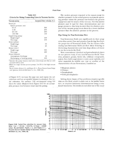
re 2-46. Typical flow velocities for vacuum lines. 2
e: 1 torr = 1.33 rnb = 133.3 Pa. 1 .O Nsec = 0.3048
m/sec. By permission, Ryans, J. L. and Roper, D. L., ,o
Process Vacuum System Design & Operation, McGraw-
Hill Book Go., lnc., 1986 [I$]. Pressure, torr