
Page 22 - APPLIED PROCESS DESIGN FOR CHEMICAL AND PETROCHEMICAL PLANTS, Volume 1, 3rd Edition
P. 22
Process Planning, Scheduling and Flowsheet Design 11
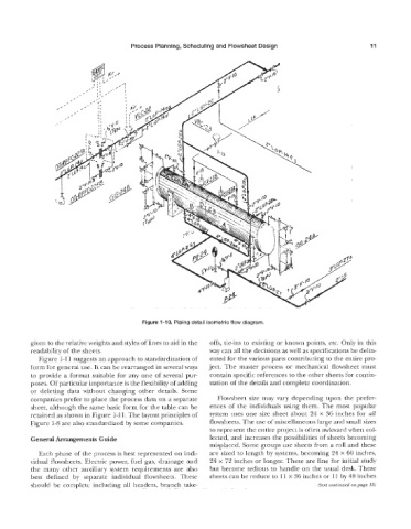
Figure 1-10, Piping detail isometric flow diagram.
given to the relative weights and styles of lines to aid in the offs, tie-ins to existing or known points, etc. Only in this
readability of the sheets. way can all the decisions as well as specifications be delin-
Figure 3-1 k suggests an approach to standardization of eated for the various parts contributing to the entire pro-
form for general use. It can be rearranged in several ways ject. The master process or mechanical flowsheet must
to provide a format suitable for any one of several pur- contain specific references to the other sheets for contin-
poses. Of particular importance is the flexibility of adding uation of the details and complete coordination.
or deleting data without changing other details. Some
companies prefer to place the process data on a separate Flowsheet size may vary depending upon the prefer-
sheet, although the same basic form for the table can be ences of the individuals using them. The most popular
retained as shown in Figure 1-11. The layout principles of system uses one size sheet about 24 x 36 inches for all
Figure 1-8 are also standardized by some companies. flowsheets. The use of miscellaneous large and small sizes
to represent the entire project is often awkward when col-
lected, and increases the possibilities of sheets becoming
misplaced. Some groups use sheets from a roll and these
Each phase of the process is best represented on indi- are sized to length by systems, becoming 24 x 60 inches,
vidual flowsheets. Electric power, fuel gas, drainage and 24 x 72 inches or longer. These are fine for initial study
the many other auxiliary system requirements are also but become tedious to handle on the usual desk. These
best defined bj7 separate individual flowsheets. These sheets can be reduce to 11 x 36 inches 01- 11 by 48 inches
should be complete including all headers, branch take- (text continued on page 151