
Page 262 - APPLIED PROCESS DESIGN FOR CHEMICAL AND PETROCHEMICAL PLANTS, Volume 1, 3rd Edition
P. 262
234 Applied Process Design for Chemical and Petrochemical Plants
Remarks from Table 4-5 (Cont.) and other fine additions make collection and dust free di5
posal difficult.
44. Often no collection equipment is used where dispersion from
38. Dust ranges from chips to fine floats including graphitic exhaust stack is good and stack location favorable.
carbon. 45. Salvage of collected material often dictates type of high
39. Materials involved vary widely. Collector selection may de- efficiency collector.
pend on salvage value, toxicity, sanitation yardsticks. 46. Fire hazard from some operations must be considered.
40. Controlled temperature and humidity of supply air to coat- 47. Bulky material. Storage for collected material is consider-
ing pans makes recirculation from coating pans desirable. able, bridging from splinters and chips can be a problem.
41. Manufacture of plastic compounds involve operations allied 48. Production sanding produces heavy concentration of par-
to many in chemical field and vary with the basic process ticles too fine to be effectively caught by cyclones or dry
employed. centrifugals.
42. Operations are similar to woodworking and collector selection 49. Primary collector invariably indicated with concentration and
involves similar considerations. See Item 13. partial size range involved, wet or fabric collectors when
43. Concentration is heavy during feed operation. Carbon black used are employed as final collectors.
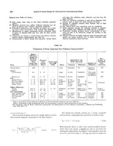
Table 4-6
Comparison of Some Important Dust Collector Characteristics*
Higher
Efficiency
Range on
Particles Max.
Greater Pressure SENSIVITY TO Temp., F,
than Loss, Water, Gal. CFM CHANGE Standard
Mean Size Inches per 1,000 - Humid Air Con-
n Microns Water CFM Space Pressure Efficiency Influence struction
- --
Electro-Static 0.25 % . . . . . . Large Negligible Yes Improves 500
Efficiency
Fabric:
Conventional 0.4 3 -6 . . . . . . Large As cfm Negligible May make 180
recondition-
ing difficult
Reverse Jet 0.25 3 -8 . . . . . . Moderate As cfm Negligible 200
Wet:
Packed Tower 1 -5 1%-3% 5 -10 Large As cfm
Wet Centrifugal 1 -5 2%-6 3 -5 Moderate As (cfm)2
No
Wet Dynamic 1 -2 Note 1 %to 1 Small Note 1 ”’ 1 None Unlimited
Orifice Types 1-5 2%-6 10-40 Small As cfm Varies with
or less design
Higher Efficiency :
Slightly to
Nozzle 0.5-5 2 -4 5 -10 Moderate As (cfm)2 Moderately 1 None Note 2
Venturi 0.5-2 12 -20 . . . . . . Small Unlimited
Dry Centrifugal:
Low Pressure Cycle 20-40 %-I% . . . . . . Large As (cfm)2 750
High Eff. Centrif. 10-30 3 -6 . . . . . . Moderate As (cfm)2 750
Dry Dynamic 10-20 Note 1 . . . . . . Small Note 1 750
Louver 15-60 1 -3 . . . . . . Small As (cfm)2 750
Note 1: A function of the mechanical efficiency of these combined exhauster and dust collectors.
Note 2: Precooling of high temperature gases will be necessary to prevent rapid evaporation of fine droplets.
* By permission, John M. Kane, “Operation, Application and Effectiveness of Dust Collection Equipment,” Heating and Ventilating.
Aug. 1952, Ref. (IO)
(text continuedfrom page 231) For hindered particle settling in a “more crowded”
The terminal settling velocity for single spheres can be environment, using spherical particles of uniform size:
determined using the contrasts for the flow regime.
V, = V, (1 - c)”’, ft/sec (4-12)
Referring the above to other than uniform spherical par-
ticles does not create a significant loss in accuracy for
(4-11)
industrial applications. For higher concentration, the val-
ues of V,, are lower than V,. In large particles in small ves-