
Page 267 - APPLIED PROCESS DESIGN FOR CHEMICAL AND PETROCHEMICAL PLANTS, Volume 1, 3rd Edition
P. 267
Mechanical Separations 239
I-Oil Field Separators
The American Petroleum Institute Manual on Disposal
of RejFinmy Wastes provides specific design and construc-
tion standards for AH-separators that are often used in
oilfield waste disposal1 [24] ~
Liqwid/Solid Gravity Separations,
.Sedimentation Equipment
This angle plate gravity separator removes suspensions
of solids from a dilute liquid. The unit is more compact
than a box-type seiiler due to the increased capacity
achieved by the multiple parallel plates. The concept is
fairly standard (U.S. Patent 1,458.805-year 1923) but
there are variations in some details. For effective opera-
tion, the unit must receive the mixture with definite par-
ticles having a settling velocity. The units are not totally
effective for flocculants or coagulated masses that may
have a tendency to be buoyant.
Flow through the plates must be laminar, and the criti-
cal internal areas are [25,54,61]:
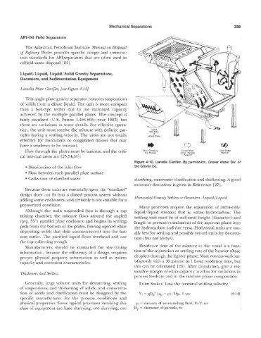
Figure 4-10. Lamella Clarifier. By permission, Graver Water Div. of
Distribution of the inlet flow the Graver Co.
Flow between each parallel plate surface
Collection oif clarified water clarifying, wastewater clarification and thickening. A good
summary discussion is given in Reference [27].
ecause these units are essentially open, the “standard”
design does not fit into a closed process system without Hol;izontal Cravity Settlers or Decanters, Liquid/Eiquid
adding some enclosures, and certainly is not suitable for a
pressurized condition. Many processes require the separation of immiscible
Although the main suspended flow is through a top liquid/liquid streams; that is, water/hydrocarbon. The
mixing chamber> the mixture flows around the angled settling unit must be of sufficient height (diameter) and
(avg. 55’) parallel plate enclosure and begins its settling length to prevent entrainment of the aqueous phase into
path from the bottsim of the plates, flowing upward while the hydrocarbon and vice versa. Horizontal units are usu-
depositing solids that slide countercurrent into the bot- ally best for settling and possibly vented units for decanta-
tom outlet. The purified liquid flows overhead and out tion (but not always).
the top collecting trlough.
Manufacturers should be contacted for size/rating Residence time of the mixture in the vessel is a func-
information, because the efficiency of a design requires tion of the separation or settling rate of the heavier phase
groper physical property information as well as system droplets through the lighter phase. Most systems work sat-
capacity and corrosion characterisrics. isfactorily with a 30 minute to 1 hour residence time, but
this can be calculated [26]. After calculation, give a rea-
sonable margin of extra capacity to allow for variations in
Thickeners and §’ettlem
process feedrate and in the mixture phase composition.
Generally, large voEurne units for dewatering, settling From Stokes’ Law, the terminal settling velocity:
of suspensions, and thickening of solids, and concentra-
tion of solids and clarification must be designed by the V, = gD,‘ (p, - p)/18p, ft sec (414)
specific manufacturer for the process conditions and
physncal properties. Some typical processes involving this p = viscosity of surrounding fluid, lb/ft sec
class of equipment are lime slurrying, ore slurrying, ore D, = diameter of particle, ft