
Page 271 - APPLIED PROCESS DESIGN FOR CHEMICAL AND PETROCHEMICAL PLANTS, Volume 1, 3rd Edition
P. 271
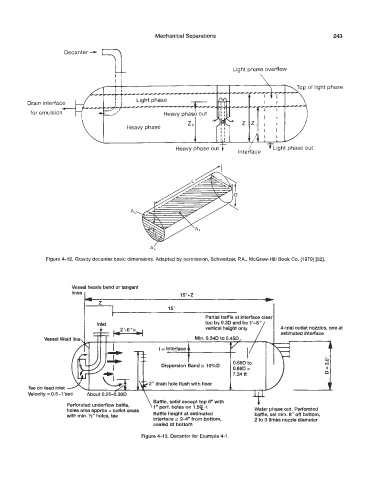
Mechanical Separations                                     243


                      Decanter  4


                                                                                                         light phase


          Drain interface
                     6.-
           for emulsion


                                                           Heavy phase out


                                                                       f l


                                            A


                                                   4

                Figure 4-12. Gri?ivity decanter basic dimensions. Adapted by permission, Schweitzer, P.A.,  McGraw-Hill Book Co. (1 979) [32].


                         Vessel heads bend or tangent
                         lines


                                                                     Partial baffle at interface clear
                                                                     top by 0.3D and be 1’4”
                                                                     vertical height only     &trial outlet nozzles, one at
                                                                                              estimated interface
                Vessel Weld line


           Tee on feed inlet -
           Velocity = 0.5-l’sec
                                                    Baffle, solid except top 6”  with   c
                         erforated underflow baffle,   \ 1“ perf. holes on 1.5% A
                        holes area approx = outlet areas                             Water phase out. Perforated
                                                         height  at  estimated        baffle, set min. 6” off bottom,
                        with min. lh’’ holes, tee   interface  24” from bottom,       2 to 3 times nozzle diameter
                                                    sealed at bottom
                                                Figure  4-13. Decanter for Example 4-1.