
Page 276 - APPLIED PROCESS DESIGN FOR CHEMICAL AND PETROCHEMICAL PLANTS, Volume 1, 3rd Edition
P. 276
248 Applied Process Design for Chemical and Petrochemical Plants
Table 4-9
Identification of Wire Mesh Types
Density, Surface Area Thickness, Min. Eff.
General Type 1 Lbs./cu. ft.* Sq. ft./cu. ft. In.** Wt. % Application
High Efficiency 12 115 4+ 99.9+ Relatively clean, moderate velocity.
Standard Eff. 9 85 4+ 99.5+ General purpose
Optimum Eff. or VH Efficiency. and
Wound type 13-14 120 4+ 99.9+ For very high efficency
Herringbone, High through-put or For services containing solids, or
Low Density 5-7 65f I 4-6+ 99.0+ “dirty” materia Is
I I 1 I
*If the mesh is made of nickel, monel or copper, multiply the density values by 1.13, referenced to stainless steel.
** 4” is minimum recommended thickness; 6” is very popular thickness: 10” and 12” recommended for special applications such as fine
mists, oil vapor mist.
Compiled from references (3) and (21).
Reference [52] suggests “dry” mesh pressure drop of: where a = specific surface area, sq ft/cu ft
f, = friction factor, dimensionless
APD = [fclapvVs/gc~3] (27.7/144) (445) g, = gravitational constant, 32.2 lb-ft/lb-sec-sec
1 = wire mesh thickness, ft
ApD = pressure drop, no entrainment, in. of water
ApL = pressure drop, due to liquid load, in. of water
For ApL see manufacturer’s curves. ApT = pressure drop, total across wet pad, in. of water
A rough approximation of operating mesh pressure V, = superficial gas velocity, ft/sec
E = void fraction of wire mesh, dimensionless
drop is 1 inch water or less. The calculated pressure drop pL = liquid density, lb/cu ft
at the maximum allowable velocity is close to 1.5 inches of py = vapor density, lb/cu ft
water. Therefore: f = generally ranges 0.2 to 2 for dry mesh
Subscript:
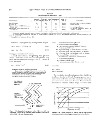
How FLEXICHEVRON@ Mist Eliminators Work Act = actual
Gases with entrained liquid droplets flow between the Max = maximum
zig-zag baffles. The gas can easily make the turns while the
liquid droplets impinge upon the walls of the baffles and
coalesce to a size such that they drop downward, The correlation factor, k, is a function of the liquid drop
being too heavy to be carried in the gas.
size, liquid viscosity, liquid load, disengaging space, type of
mesh weave, etc. k varies somewhat with system pressure; as
THE CHEVRON pressure increases the k value decreases. The manufactur-
IMPINGEMENT ers should be consulted for final design k valves for a sys-
PRINCIPLE DE-ENTRAINED GASES
DROPLET \
MIST LADEN GASES- 0 - LARGE FALLING
4 DROPLETS
FLOW 10 20 30 40
Droplet Size (microns)
Figure 4-17A. Separation/lmpingement action of Chevron-style mist
eliminators. Flow is up the V-shaped plates assembly. Courtesy of Figure 4-17B. Capture efficiency vs particle size for four standard
Bulletin KME - 12, Koch Engineering Co. York-Vane mist eliminators. By permission, Otto H. York Co. Inc.